SECTION 3 - CHASSIS & TURNTABLE
3-36
3121160
13.
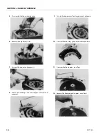
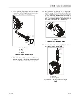
Using an 8 mm internal hex wrench, remove the endcap
screws (22).
14.
Remove the endcap (23). Remove o-ring (24) from the
housing or endcap.
When the endcap screws are removed, pressure from
the servo spring will cause the endcap to bind on the
shaft. Press down on the portion of the endcap covering
the servo piston and hold the endcap level while remov-
ing.
TAKE CARE NOT TO SCRATCH THE SURFACE OF THE VALVE PLATE.
15.
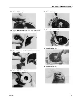
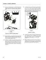
Remove the valve plate (25) and timing pin (26) from the
endcap.
Each displacement has a unique valve plate. For identifi-
cation, the last two digits of the valve plate part number
are stamped on its surface.
16.
Remove and discard the o-rings (27, 28).
17.
Remove the rear shaft bearing (29) from the endcap
with a bearing puller.
The bearing may be difficult to remove with a puller. Try
this as an alternative: Pack the bearing cavity with heavy
grease. After the shaft is removed, insert it into the bear-
ing cavity and tap lightly with a soft mallet on the
splined end. The grease will force the bearing out. Use
caution not to drive the bearing past the rear shaft jour-
nal as the bearing may become trapped on the shaft
and damaged.
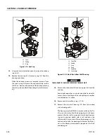
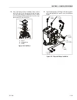
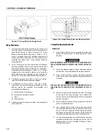
24
22
23
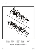
22. Screw
23. End Cap
24. O-ring
Figure 3-19. End Cap
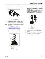
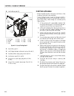
26
28
29
30
29
27
25
25. Valve Plate
26. End Cap
27. O-ring
28. O-ring
29. Angle Stop
30. Servo Spring
Figure 3-20. Valve Plate & Rear Shaft Bearing
Summary of Contents for 740AJ
Page 2: ......
Page 55: ...SECTION 3 CHASSIS TURNTABLE 3121160 3 3 This page left blank intentionally...
Page 116: ...SECTION 3 CHASSIS TURNTABLE 3 64 3121160 Figure 3 44 Swing Hub Prior to SN 0300074383...
Page 203: ...SECTION 3 CHASSIS TURNTABLE 3121160 3 151 Figure 3 77 EFI Component Location...
Page 206: ...SECTION 3 CHASSIS TURNTABLE 3 154 3121160 Figure 3 78 ECM EPM Identification ECM EPM...
Page 224: ...SECTION 3 CHASSIS TURNTABLE 3 172 3121160 Figure 3 83 Deutz EMR 2 Troubleshooting Flow Chart...
Page 228: ...SECTION 3 CHASSIS TURNTABLE 3 176 3121160 Figure 3 87 EMR 2 Engine Plug Pin Identification...
Page 229: ...SECTION 3 CHASSIS TURNTABLE 3121160 3 177 Figure 3 88 EMR 2 Vehicle Plug Pin Identification...
Page 230: ...SECTION 3 CHASSIS TURNTABLE 3 178 3121160 Figure 3 89 EMR2 Fault Codes Sheet 1 of 5...
Page 231: ...SECTION 3 CHASSIS TURNTABLE 3121160 3 179 Figure 3 90 EMR2 Fault Codes Sheet 2 of 5...
Page 232: ...SECTION 3 CHASSIS TURNTABLE 3 180 3121160 Figure 3 91 EMR2 Fault Codes Sheet 3 of 5...
Page 233: ...SECTION 3 CHASSIS TURNTABLE 3121160 3 181 Figure 3 92 EMR2 Fault Codes Sheet 4 of 5...
Page 234: ...SECTION 3 CHASSIS TURNTABLE 3 182 3121160 Figure 3 93 EMR2 Fault Codes Sheet 5 of 5...
Page 303: ...SECTION 4 BOOM PLATFORM 3121160 4 31 Figure 4 20 Rotator Assembly HELAC...
Page 460: ...SECTION 5 BASIC HYDRAULIC INFORMATION AND SCHEMATICS 5 116 3121160 NOTES...
Page 467: ...SECTION 6 JLG CONTROL SYSTEM 3121160 6 7 Figure 6 2 ADE Block Diagram...
Page 534: ...SECTION 6 JLG CONTROL SYSTEM 6 74 3121160 NOTES...
Page 580: ...SECTION 7 BASIC ELECTRICAL INFORMATION SCHEMATICS 7 46 3121160 NOTES...
Page 581: ......

