


SECTION 3 - CHASSIS & TURNTABLE
3121160
3-113
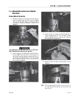
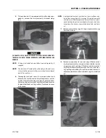
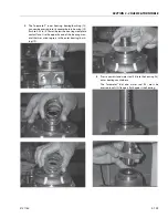
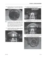
14.
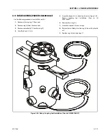
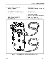
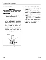
Apply clean grease to a new seal ring (4) and assemble it
in the seal ring groove in the rotor set contact side of
manifold (7).
NOTE:
The manifold (7) is made up of several plates bonded
together permanently to form an integral component. The
manifold surface that must contact the rotor set has it’s
series of irregular shaped cavities on the largest circumfer-
ence or circle around the inside diameter. The polished
impression left on the manifold by the rotor set is another
indication of which surface must contact the rotor set.
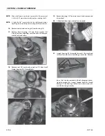
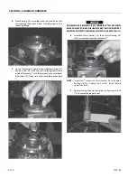
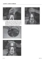
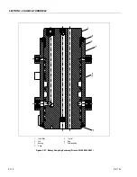
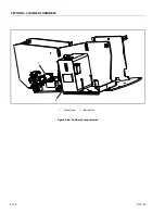
15.
Assemble the manifold (7) over the alignment studs and
drive link (10) and onto the rotor set. Be sure the correct
manifold surface is against the rotor set.
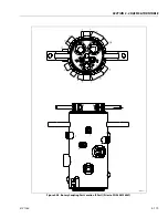
16.
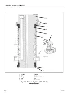
Apply grease to a new seal ring (4) and insert it in the
seal ring groove exposed on the manifold.
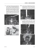
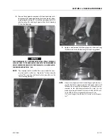
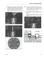
17.
Assemble the commutator ring (6) over alignment studs
onto the manifold.
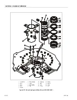
18.
Assemble a new seal ring (3) flat side up, into commuta-
tor (5) and assemble commutator over the end of drive
link (10) onto manifold (7) with seal ring side up.
Summary of Contents for 740AJ
Page 2: ......
Page 55: ...SECTION 3 CHASSIS TURNTABLE 3121160 3 3 This page left blank intentionally...
Page 116: ...SECTION 3 CHASSIS TURNTABLE 3 64 3121160 Figure 3 44 Swing Hub Prior to SN 0300074383...
Page 203: ...SECTION 3 CHASSIS TURNTABLE 3121160 3 151 Figure 3 77 EFI Component Location...
Page 206: ...SECTION 3 CHASSIS TURNTABLE 3 154 3121160 Figure 3 78 ECM EPM Identification ECM EPM...
Page 224: ...SECTION 3 CHASSIS TURNTABLE 3 172 3121160 Figure 3 83 Deutz EMR 2 Troubleshooting Flow Chart...
Page 228: ...SECTION 3 CHASSIS TURNTABLE 3 176 3121160 Figure 3 87 EMR 2 Engine Plug Pin Identification...
Page 229: ...SECTION 3 CHASSIS TURNTABLE 3121160 3 177 Figure 3 88 EMR 2 Vehicle Plug Pin Identification...
Page 230: ...SECTION 3 CHASSIS TURNTABLE 3 178 3121160 Figure 3 89 EMR2 Fault Codes Sheet 1 of 5...
Page 231: ...SECTION 3 CHASSIS TURNTABLE 3121160 3 179 Figure 3 90 EMR2 Fault Codes Sheet 2 of 5...
Page 232: ...SECTION 3 CHASSIS TURNTABLE 3 180 3121160 Figure 3 91 EMR2 Fault Codes Sheet 3 of 5...
Page 233: ...SECTION 3 CHASSIS TURNTABLE 3121160 3 181 Figure 3 92 EMR2 Fault Codes Sheet 4 of 5...
Page 234: ...SECTION 3 CHASSIS TURNTABLE 3 182 3121160 Figure 3 93 EMR2 Fault Codes Sheet 5 of 5...
Page 303: ...SECTION 4 BOOM PLATFORM 3121160 4 31 Figure 4 20 Rotator Assembly HELAC...
Page 460: ...SECTION 5 BASIC HYDRAULIC INFORMATION AND SCHEMATICS 5 116 3121160 NOTES...
Page 467: ...SECTION 6 JLG CONTROL SYSTEM 3121160 6 7 Figure 6 2 ADE Block Diagram...
Page 534: ...SECTION 6 JLG CONTROL SYSTEM 6 74 3121160 NOTES...
Page 580: ...SECTION 7 BASIC ELECTRICAL INFORMATION SCHEMATICS 7 46 3121160 NOTES...
Page 581: ......