SECTION 3 - CHASSIS & TURNTABLE
3-194
3121160
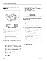
Electronic Throttle Control Replacement
REMOVAL
1.
Disconnect the negative battery cable.
2.
Remove the air intake duct.
3.
Release the hose clamp on the vapor fuel line and
remove the vapor hose.
4.
Disconnect the TMAP electrical connector.
5.
Disconnect the electronic throttle control connector.
6.
Remove the manifold to throttle body adapter bolts and
remove the throttle body mixer assembly.
7.
Pull the throttle body assembly from the adapter.
8.
Remove electronic throttle control device.
9.
Remove the O-rings gasket and discard.
INSTALLATION
LIGHTLY LUBRICATE BOTH THROTTLE CONTROL DEVICE TO ADAPTER O-RINGS.
1.
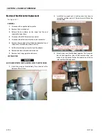
Install the o-ring on throttle body. Press it down to the
bottom of the surface.
2.
Install the two quad seals. Install one seal at a time to
insure the seal does not roll. The seal must sit flat on the
throttle body.
3.
Attach mixer and throttle body together. The two parts
do not bolt together; they will be secured when you
mount it on the intake. Notice the orientation of the air
inlet and throttle body cover.
Summary of Contents for 740AJ
Page 2: ......
Page 55: ...SECTION 3 CHASSIS TURNTABLE 3121160 3 3 This page left blank intentionally...
Page 116: ...SECTION 3 CHASSIS TURNTABLE 3 64 3121160 Figure 3 44 Swing Hub Prior to SN 0300074383...
Page 203: ...SECTION 3 CHASSIS TURNTABLE 3121160 3 151 Figure 3 77 EFI Component Location...
Page 206: ...SECTION 3 CHASSIS TURNTABLE 3 154 3121160 Figure 3 78 ECM EPM Identification ECM EPM...
Page 224: ...SECTION 3 CHASSIS TURNTABLE 3 172 3121160 Figure 3 83 Deutz EMR 2 Troubleshooting Flow Chart...
Page 228: ...SECTION 3 CHASSIS TURNTABLE 3 176 3121160 Figure 3 87 EMR 2 Engine Plug Pin Identification...
Page 229: ...SECTION 3 CHASSIS TURNTABLE 3121160 3 177 Figure 3 88 EMR 2 Vehicle Plug Pin Identification...
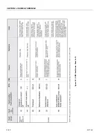
Page 230: ...SECTION 3 CHASSIS TURNTABLE 3 178 3121160 Figure 3 89 EMR2 Fault Codes Sheet 1 of 5...
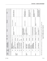
Page 231: ...SECTION 3 CHASSIS TURNTABLE 3121160 3 179 Figure 3 90 EMR2 Fault Codes Sheet 2 of 5...
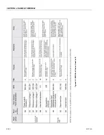
Page 232: ...SECTION 3 CHASSIS TURNTABLE 3 180 3121160 Figure 3 91 EMR2 Fault Codes Sheet 3 of 5...
Page 233: ...SECTION 3 CHASSIS TURNTABLE 3121160 3 181 Figure 3 92 EMR2 Fault Codes Sheet 4 of 5...
Page 234: ...SECTION 3 CHASSIS TURNTABLE 3 182 3121160 Figure 3 93 EMR2 Fault Codes Sheet 5 of 5...
Page 303: ...SECTION 4 BOOM PLATFORM 3121160 4 31 Figure 4 20 Rotator Assembly HELAC...
Page 460: ...SECTION 5 BASIC HYDRAULIC INFORMATION AND SCHEMATICS 5 116 3121160 NOTES...
Page 467: ...SECTION 6 JLG CONTROL SYSTEM 3121160 6 7 Figure 6 2 ADE Block Diagram...
Page 534: ...SECTION 6 JLG CONTROL SYSTEM 6 74 3121160 NOTES...
Page 580: ...SECTION 7 BASIC ELECTRICAL INFORMATION SCHEMATICS 7 46 3121160 NOTES...
Page 581: ......

