


SECTION 3 - CHASSIS & TURNTABLE
3121160
3-59
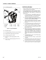
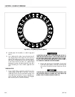
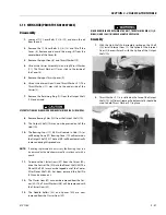
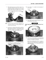
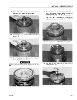
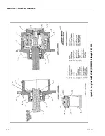
7.
While holding Ring Gear (4) and Cluster Gears (3F) in
mesh, place small side of Cluster Gears (3F) into mesh
with the Internal Gear (2) and Input Gear (13). On the
Ring Gear locate the hole marked X over one of the
marked counterbored holes (Step 3) in Hub (1G).
NOTE:
If gears do not mesh easily or Carrier Assembly does not
rotate freely, then remove the Carrier and Ring Gear and
check the Cluster Gear timing.
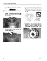
8.
Input Gear (8) is installed, meshing with the teeth of the
large diameter Cluster Gear (3F). The counterbore on the
Input Gear (8) locates on the shoulder of the Thrust
Spacer (9). This is to be a slip fit and operate freely.
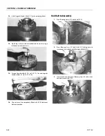
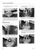
9.
Thrust Washer (10) is installed onto the Input Gear (8)
and should locate on the gear teeth shoulder.
10.
Thrust Washer (11) is installed into the counterbore of
the Carrier (3).
11.
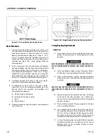
Place O-ring (5) into Cover (6) counterbore. Use petro-
leum jelly to hold O-ring in place.
BEWARE OF SHARP EDGES OF THE COUNTERBORE WHILE SEATING THIS O-
RING.
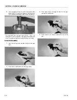
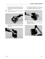
12.
The Cover (6) is now installed on this assembly. Taking
care to correctly align Pipe Plug hole (20) with those in
the Hub (1J), usually 90° to one another.
Locate the 4 counterbore holes in Hub (1G) (marked in
Step 3) and install 4 Shoulder Bolts (13). A slight tap with
a hammer may be necessary to align Shoulder Bolt with
Hub (1G) counterbore.
Summary of Contents for 740AJ
Page 2: ......
Page 55: ...SECTION 3 CHASSIS TURNTABLE 3121160 3 3 This page left blank intentionally...
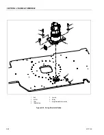
Page 116: ...SECTION 3 CHASSIS TURNTABLE 3 64 3121160 Figure 3 44 Swing Hub Prior to SN 0300074383...
Page 203: ...SECTION 3 CHASSIS TURNTABLE 3121160 3 151 Figure 3 77 EFI Component Location...
Page 206: ...SECTION 3 CHASSIS TURNTABLE 3 154 3121160 Figure 3 78 ECM EPM Identification ECM EPM...
Page 224: ...SECTION 3 CHASSIS TURNTABLE 3 172 3121160 Figure 3 83 Deutz EMR 2 Troubleshooting Flow Chart...
Page 228: ...SECTION 3 CHASSIS TURNTABLE 3 176 3121160 Figure 3 87 EMR 2 Engine Plug Pin Identification...
Page 229: ...SECTION 3 CHASSIS TURNTABLE 3121160 3 177 Figure 3 88 EMR 2 Vehicle Plug Pin Identification...
Page 230: ...SECTION 3 CHASSIS TURNTABLE 3 178 3121160 Figure 3 89 EMR2 Fault Codes Sheet 1 of 5...
Page 231: ...SECTION 3 CHASSIS TURNTABLE 3121160 3 179 Figure 3 90 EMR2 Fault Codes Sheet 2 of 5...
Page 232: ...SECTION 3 CHASSIS TURNTABLE 3 180 3121160 Figure 3 91 EMR2 Fault Codes Sheet 3 of 5...
Page 233: ...SECTION 3 CHASSIS TURNTABLE 3121160 3 181 Figure 3 92 EMR2 Fault Codes Sheet 4 of 5...
Page 234: ...SECTION 3 CHASSIS TURNTABLE 3 182 3121160 Figure 3 93 EMR2 Fault Codes Sheet 5 of 5...
Page 303: ...SECTION 4 BOOM PLATFORM 3121160 4 31 Figure 4 20 Rotator Assembly HELAC...
Page 460: ...SECTION 5 BASIC HYDRAULIC INFORMATION AND SCHEMATICS 5 116 3121160 NOTES...
Page 467: ...SECTION 6 JLG CONTROL SYSTEM 3121160 6 7 Figure 6 2 ADE Block Diagram...
Page 534: ...SECTION 6 JLG CONTROL SYSTEM 6 74 3121160 NOTES...
Page 580: ...SECTION 7 BASIC ELECTRICAL INFORMATION SCHEMATICS 7 46 3121160 NOTES...
Page 581: ......