SECTION 2 - GENERAL
2-6
3121160
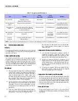
2.5
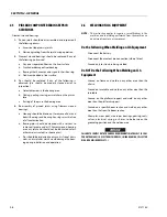
PINS AND COMPOSITE BEARING REPAIR
GUIDELINES
Filament wound bearings.
1.
Pinned joints should be disassembled and inspected if
the following occurs:
a. Excessive sloppiness in joints.
b. Noise originating from the joint during operation.
2.
Filament wound bearings should be replaced if any of
the following is observed:
a. Frayed or separated fibers on the liner surface.
b. Cracked or damaged liner backing.
c. Bearings that have moved or spun in their housing.
d. Debris embedded in liner surface.
3.
Pins should be replaced if any of the following is
observed (pin should be properly cleaned prior to
inspection):
a. Detectable wear in the bearing area.
b. Flaking, pealing, scoring, or scratches on the pin sur-
face.
c. Rusting of the pin in the bearing area.
4.
Re-assembly of pinned joints using filament wound
bearings.
a. Housing should be blown out to remove all dirt and
debris. Bearings and bearing housings must be free
of all contamination.
b. Bearing/pins should be cleaned with a solvent to
remove all grease and oil. Filament wound bearing
are a dry joint and should not be lubricated unless
otherwise instructed (i.e. sheave pins).
c. Pins should be inspected to ensure it is free of burrs,
nicks, and scratches which would damage the bear-
ing during installation and operation.
2.6
WELDING ON JLG EQUIPMENT
NOTE:
This instruction applies to repairs, or modifications to the
machine and to welding performed from the machine on
an external structure, or component.
Do the Following When Welding on JLG Equipment
• Disconnect the battery.
• Disconnect the moment pin connection (where fitted).
• Ground only to structure being welded.
Do NOT Do the Following When Welding on JLG
Equipment
• Ground on frame and weld on any other area than the
chassis.
• Ground on turntable and weld on any other area than the
turntable.
• Ground on the platform/support and weld on any other
area than the platform/support.
• Ground on a specific boom section and weld on any other
area than that specific boom section.
• Allow pins, wear pads, wire ropes, bearings, gearing, seals,
valves, electrical wiring, or hoses to be between the
grounding position and the welded area.
FAILURE TO COMPLY WITH THE ABOVE REQUIREMENTS MAY RESULT IN COM-
PONENT DAMAGE (I.E. ELECTRONIC MODULES, SWING BEARING, COLLECTOR
RING, BOOM WIRE ROPES ETC.).
Summary of Contents for 740AJ
Page 2: ......
Page 55: ...SECTION 3 CHASSIS TURNTABLE 3121160 3 3 This page left blank intentionally...
Page 116: ...SECTION 3 CHASSIS TURNTABLE 3 64 3121160 Figure 3 44 Swing Hub Prior to SN 0300074383...
Page 203: ...SECTION 3 CHASSIS TURNTABLE 3121160 3 151 Figure 3 77 EFI Component Location...
Page 206: ...SECTION 3 CHASSIS TURNTABLE 3 154 3121160 Figure 3 78 ECM EPM Identification ECM EPM...
Page 224: ...SECTION 3 CHASSIS TURNTABLE 3 172 3121160 Figure 3 83 Deutz EMR 2 Troubleshooting Flow Chart...
Page 228: ...SECTION 3 CHASSIS TURNTABLE 3 176 3121160 Figure 3 87 EMR 2 Engine Plug Pin Identification...
Page 229: ...SECTION 3 CHASSIS TURNTABLE 3121160 3 177 Figure 3 88 EMR 2 Vehicle Plug Pin Identification...
Page 230: ...SECTION 3 CHASSIS TURNTABLE 3 178 3121160 Figure 3 89 EMR2 Fault Codes Sheet 1 of 5...
Page 231: ...SECTION 3 CHASSIS TURNTABLE 3121160 3 179 Figure 3 90 EMR2 Fault Codes Sheet 2 of 5...
Page 232: ...SECTION 3 CHASSIS TURNTABLE 3 180 3121160 Figure 3 91 EMR2 Fault Codes Sheet 3 of 5...
Page 233: ...SECTION 3 CHASSIS TURNTABLE 3121160 3 181 Figure 3 92 EMR2 Fault Codes Sheet 4 of 5...
Page 234: ...SECTION 3 CHASSIS TURNTABLE 3 182 3121160 Figure 3 93 EMR2 Fault Codes Sheet 5 of 5...
Page 303: ...SECTION 4 BOOM PLATFORM 3121160 4 31 Figure 4 20 Rotator Assembly HELAC...
Page 460: ...SECTION 5 BASIC HYDRAULIC INFORMATION AND SCHEMATICS 5 116 3121160 NOTES...
Page 467: ...SECTION 6 JLG CONTROL SYSTEM 3121160 6 7 Figure 6 2 ADE Block Diagram...
Page 534: ...SECTION 6 JLG CONTROL SYSTEM 6 74 3121160 NOTES...
Page 580: ...SECTION 7 BASIC ELECTRICAL INFORMATION SCHEMATICS 7 46 3121160 NOTES...
Page 581: ......

