SECTION 5 - BASIC HYDRAULIC INFOR
M
ATION AND SCHE
M
ATICS
3121160
5-85
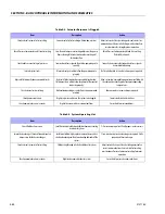
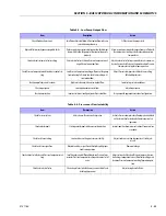
Table 5-5. Low Pump Output Flow
Item
Description
Action
Check fluid level in reservoir.
Insufficient hydraulic fluid will limit output flow and cause
internal damage to pump.
Fill the reservoir to proper level.
Hydraulic fluid viscosity above acceptable limits.
Fluid viscosity above acceptable limits or low fluid temper-
ature will not allow the pump to fill or control to operate
properly.
Allow system to warm up before operation or use fluid with
the appropriate viscosity grade for expected operating
temperatures.
Check external system relief valve setting.
External relief valve set below Pressure Compensator set-
ting will cause low output flow.
Adjust external relief valve per manufacturer’s recommen-
dation. External relief valve setting must be above Pressure
Compensator setting for proper operation.
Check Pressure Compensator and Load Sense control set-
ting.
Low Pressure Compensator setting will prevent the pump
from achieving full stroke. Low Load Sense setting will
limit output flow.
Adjust Pressure Compensator and Load Sense setting.
Refer to Adjustments.
Check pump inlet pressure / vacuum.
High inlet vacuum will cause low output flow.
Correct inlet pressure conditions.
Check input speed.
Low input speeds decrease flow.
Adjust input speed.
Check pump rotation.
Incorrect rotational configuration will cause low flow.
Use pump with appropriate rotational configuration.
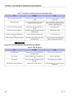
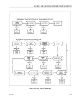
Table 5-6. Pressure or Flow Instability
Item
Description
Action
Check for air in system.
Air in system will cause erratic operation.
Activate Pressure Compensator, allowing system to bleed
air. Check inlet line for leaks and eliminate source of air
ingression.
Check control spools.
Sticking control spools will cause erratic operation.
Inspect spools for free movement in bore. Clean or replace
as needed.
Check Load Sense setting.
Low Load Sense setting may cause instability.
Adjust Load Sense setting to proper level. See Adjust-
ments.
Check Load Sense signal line.
Blocked Load Sense signal line will interfere with proper
Load Sense operation.
Remove blockage.
Check external relief valve and Pressure Compensator set-
ting.
Insufficient pressure differential between Pressure Com-
pensator Pressure Compensator setting and external relief
valve.
Adjust external relief valve or Pressure Compensator con-
trol settings to appropriate level. Relief valve setting must
be above Pressure Compensator setting for proper opera-
tion.
Check external relief valve.
Chattering external relief valve may cause unstable feed-
back to pump control.
Adjust or replace relief valve.
Summary of Contents for 740AJ
Page 2: ......
Page 55: ...SECTION 3 CHASSIS TURNTABLE 3121160 3 3 This page left blank intentionally...
Page 116: ...SECTION 3 CHASSIS TURNTABLE 3 64 3121160 Figure 3 44 Swing Hub Prior to SN 0300074383...
Page 203: ...SECTION 3 CHASSIS TURNTABLE 3121160 3 151 Figure 3 77 EFI Component Location...
Page 206: ...SECTION 3 CHASSIS TURNTABLE 3 154 3121160 Figure 3 78 ECM EPM Identification ECM EPM...
Page 224: ...SECTION 3 CHASSIS TURNTABLE 3 172 3121160 Figure 3 83 Deutz EMR 2 Troubleshooting Flow Chart...
Page 228: ...SECTION 3 CHASSIS TURNTABLE 3 176 3121160 Figure 3 87 EMR 2 Engine Plug Pin Identification...
Page 229: ...SECTION 3 CHASSIS TURNTABLE 3121160 3 177 Figure 3 88 EMR 2 Vehicle Plug Pin Identification...
Page 230: ...SECTION 3 CHASSIS TURNTABLE 3 178 3121160 Figure 3 89 EMR2 Fault Codes Sheet 1 of 5...
Page 231: ...SECTION 3 CHASSIS TURNTABLE 3121160 3 179 Figure 3 90 EMR2 Fault Codes Sheet 2 of 5...
Page 232: ...SECTION 3 CHASSIS TURNTABLE 3 180 3121160 Figure 3 91 EMR2 Fault Codes Sheet 3 of 5...
Page 233: ...SECTION 3 CHASSIS TURNTABLE 3121160 3 181 Figure 3 92 EMR2 Fault Codes Sheet 4 of 5...
Page 234: ...SECTION 3 CHASSIS TURNTABLE 3 182 3121160 Figure 3 93 EMR2 Fault Codes Sheet 5 of 5...
Page 303: ...SECTION 4 BOOM PLATFORM 3121160 4 31 Figure 4 20 Rotator Assembly HELAC...
Page 460: ...SECTION 5 BASIC HYDRAULIC INFORMATION AND SCHEMATICS 5 116 3121160 NOTES...
Page 467: ...SECTION 6 JLG CONTROL SYSTEM 3121160 6 7 Figure 6 2 ADE Block Diagram...
Page 534: ...SECTION 6 JLG CONTROL SYSTEM 6 74 3121160 NOTES...
Page 580: ...SECTION 7 BASIC ELECTRICAL INFORMATION SCHEMATICS 7 46 3121160 NOTES...
Page 581: ......

