


SECTION 7 - BASIC ELECTRICAL INFOR
M
ATION & SCHE
M
ATICS
7-4
3121160
3.
Anderson connectors for the battery boxes and battery
chargers should have silicone grease applied to the con-
tacts only.
NOTE:
Curing-type sealants might also be used to prevent short-
ing and would be less messy, but would make future pin
removal more difficult.
When applied to electrical connections, dielectric grease helps
to prevent corrosion of electrical contacts and improper con-
ductivity between contacts from moisture intrusion. Open and
sealed connectors benefit from the application of dielectric
grease.
Dielectric grease shall be applied to all electrical connectors at
the time of connection (except those noted under Exclusions).
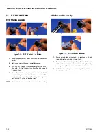
Installation of Dielectric Grease
Before following these instructions, refer to excluded connec-
tor types (See Exclusions below).
1.
Use dielectric grease in a tube for larger connection
points or apply with a syringe for small connectors.
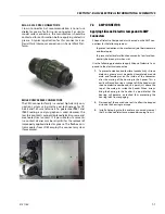
2.
Apply dielectric grease to the female contact (fill it
approximately ½ full; see example below).
3.
Leave a thin layer of dielectric grease on the face of the
connector.
4.
Assemble the connector system immediately to prevent
moisture ingress or dust contamination.
5.
Pierce one of the unused wire seals prior to assembly if
the connector system tends to trap air (i.e. AMP Seal)
and then install a seal plug.
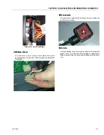
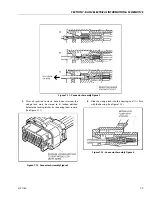
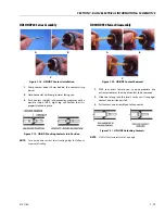
Deutsch HD, DT, DTM, DRC Series
The Deutsch connector system is commonly used for harsh
environment interconnect. Follow the installation instructions.
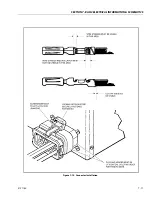
AWP Seal
The AMP Seal connector system is used on the Control ADE
Platform and Ground Modules.
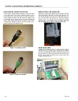
Apply dielectric grease to the female contact. If trapped air
prevents the connector from latching, pierce one of the
unused wire seals. After assembly, install a seal plug (JLG
#4460905) in that location to prevent moisture ingress.
Note that seal plugs may be installed by the wire harness man-
ufacturer if an unused wire seal becomes compromised (wire
inserted in the wrong cavity during assembly and then cor-
rected).
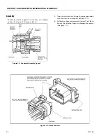
Figure 7-5. Application to plug/male connector housing
Summary of Contents for 740AJ
Page 2: ......
Page 55: ...SECTION 3 CHASSIS TURNTABLE 3121160 3 3 This page left blank intentionally...
Page 116: ...SECTION 3 CHASSIS TURNTABLE 3 64 3121160 Figure 3 44 Swing Hub Prior to SN 0300074383...
Page 203: ...SECTION 3 CHASSIS TURNTABLE 3121160 3 151 Figure 3 77 EFI Component Location...
Page 206: ...SECTION 3 CHASSIS TURNTABLE 3 154 3121160 Figure 3 78 ECM EPM Identification ECM EPM...
Page 224: ...SECTION 3 CHASSIS TURNTABLE 3 172 3121160 Figure 3 83 Deutz EMR 2 Troubleshooting Flow Chart...
Page 228: ...SECTION 3 CHASSIS TURNTABLE 3 176 3121160 Figure 3 87 EMR 2 Engine Plug Pin Identification...
Page 229: ...SECTION 3 CHASSIS TURNTABLE 3121160 3 177 Figure 3 88 EMR 2 Vehicle Plug Pin Identification...
Page 230: ...SECTION 3 CHASSIS TURNTABLE 3 178 3121160 Figure 3 89 EMR2 Fault Codes Sheet 1 of 5...
Page 231: ...SECTION 3 CHASSIS TURNTABLE 3121160 3 179 Figure 3 90 EMR2 Fault Codes Sheet 2 of 5...
Page 232: ...SECTION 3 CHASSIS TURNTABLE 3 180 3121160 Figure 3 91 EMR2 Fault Codes Sheet 3 of 5...
Page 233: ...SECTION 3 CHASSIS TURNTABLE 3121160 3 181 Figure 3 92 EMR2 Fault Codes Sheet 4 of 5...
Page 234: ...SECTION 3 CHASSIS TURNTABLE 3 182 3121160 Figure 3 93 EMR2 Fault Codes Sheet 5 of 5...
Page 303: ...SECTION 4 BOOM PLATFORM 3121160 4 31 Figure 4 20 Rotator Assembly HELAC...
Page 460: ...SECTION 5 BASIC HYDRAULIC INFORMATION AND SCHEMATICS 5 116 3121160 NOTES...
Page 467: ...SECTION 6 JLG CONTROL SYSTEM 3121160 6 7 Figure 6 2 ADE Block Diagram...
Page 534: ...SECTION 6 JLG CONTROL SYSTEM 6 74 3121160 NOTES...
Page 580: ...SECTION 7 BASIC ELECTRICAL INFORMATION SCHEMATICS 7 46 3121160 NOTES...
Page 581: ......