SECTION 5 - BASIC HYDRAULIC INFOR
M
ATION AND SCHE
M
ATICS
5-80
3121160
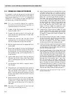
INADEQUATE CHARGE PRESSURE WILL AFFECT THE OPERATOR'S ABILITY TO
CONTROL THE MACHINE.
Shut down the engine and connect the external control input
signal. Also reconnect the machine function(s), if discon-
nected earlier. Start the engine, checking to be certain the
pump remains in neutral. With the engine at normal operating
RPM, slowly check for forward and reverse machine operation.
Charge pressure may slightly decrease during forward or
reverse operation. Continue to cycle slowly between forward
and reverse for at least five minutes.
Shut down engine, remove gauges, and plug ports. Check res-
ervoir level and add filtered fluid if needed.
The machine is now ready for operation.
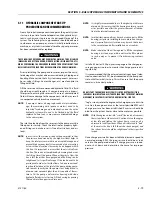
5.12
REXROTH VARIABLE DISPLACEMENT PUMP
(PRIOR TO SN 0300121643)
The variable displacement axial piston pump is a swashplate
design for hydrostatic drives in open circuits. The flow is pro-
portional to the speed and the displacement. By adjusting the
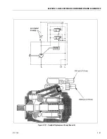
swashplate, it is possible to vary the flow steplessly. See Figure
2-43 for pressure settings and schematic.
1.
Variable, swashplate design SAE nominal pressure 3600
psi (248 bar), peak pressure 4600 psi (317 bar).
2.
Pump, open circuit.
3.
Displacement Vgmax 2.75 in
3
(45 cm
3
).
4.
Pressure and flow control (DFR1).
5.
Series 52.
6.
Clockwise rotation.
7.
NBR seals (Nitrile rubber to DIN ISO 1629).
8.
SAE 1.00 in. (2.54 cm) splined shaft.(not suitable for
through drive).
9.
SAE 2 bolt mounting Flange - SAE 101-2 (B).
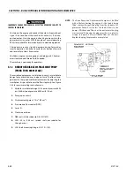
NOTE:
The Drive Pump and Displacement Pump must be filled
with oil before starting the engine. As the tank is being
filled, remove the specified plug from the Variable Dis-
placement Pump. As oil enters the tank it flows to the
pumps, fills them and flows out the port where the plug
was removed. Removing the plug gives the air a place to
escape. In approx. 5 min.,oil should flow out the port.
Replace the plug, the procedure is completed.
Summary of Contents for 740AJ
Page 2: ......
Page 55: ...SECTION 3 CHASSIS TURNTABLE 3121160 3 3 This page left blank intentionally...
Page 116: ...SECTION 3 CHASSIS TURNTABLE 3 64 3121160 Figure 3 44 Swing Hub Prior to SN 0300074383...
Page 203: ...SECTION 3 CHASSIS TURNTABLE 3121160 3 151 Figure 3 77 EFI Component Location...
Page 206: ...SECTION 3 CHASSIS TURNTABLE 3 154 3121160 Figure 3 78 ECM EPM Identification ECM EPM...
Page 224: ...SECTION 3 CHASSIS TURNTABLE 3 172 3121160 Figure 3 83 Deutz EMR 2 Troubleshooting Flow Chart...
Page 228: ...SECTION 3 CHASSIS TURNTABLE 3 176 3121160 Figure 3 87 EMR 2 Engine Plug Pin Identification...
Page 229: ...SECTION 3 CHASSIS TURNTABLE 3121160 3 177 Figure 3 88 EMR 2 Vehicle Plug Pin Identification...
Page 230: ...SECTION 3 CHASSIS TURNTABLE 3 178 3121160 Figure 3 89 EMR2 Fault Codes Sheet 1 of 5...
Page 231: ...SECTION 3 CHASSIS TURNTABLE 3121160 3 179 Figure 3 90 EMR2 Fault Codes Sheet 2 of 5...
Page 232: ...SECTION 3 CHASSIS TURNTABLE 3 180 3121160 Figure 3 91 EMR2 Fault Codes Sheet 3 of 5...
Page 233: ...SECTION 3 CHASSIS TURNTABLE 3121160 3 181 Figure 3 92 EMR2 Fault Codes Sheet 4 of 5...
Page 234: ...SECTION 3 CHASSIS TURNTABLE 3 182 3121160 Figure 3 93 EMR2 Fault Codes Sheet 5 of 5...
Page 303: ...SECTION 4 BOOM PLATFORM 3121160 4 31 Figure 4 20 Rotator Assembly HELAC...
Page 460: ...SECTION 5 BASIC HYDRAULIC INFORMATION AND SCHEMATICS 5 116 3121160 NOTES...
Page 467: ...SECTION 6 JLG CONTROL SYSTEM 3121160 6 7 Figure 6 2 ADE Block Diagram...
Page 534: ...SECTION 6 JLG CONTROL SYSTEM 6 74 3121160 NOTES...
Page 580: ...SECTION 7 BASIC ELECTRICAL INFORMATION SCHEMATICS 7 46 3121160 NOTES...
Page 581: ......

