SECTION
4
- BOO
M
& PLATFOR
M
4-20
3121160
Installation
1.
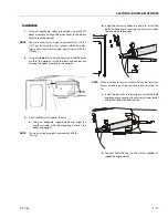
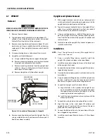
Using a suitable lifting device, position the tower boom
such as to align upright leveling cylinder with attach
holes in tower boom. Using a soft head mallet, install the
cylinder pin into tower boom and secure with mounting
hardware.
2.
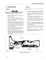
Using a suitable lifting device, position boom assembly
on turntable so that the pivot holes in both boom and
turntable are aligned.
3.
Install boom pivot pin, ensuring that location of hole in
pin is aligned with attach point on turntable.
4.
If necessary, gently tap pin into position with soft
headed mallet. Secure pin mounting hardware.
5.
Connect all wiring connectors to the correct connectors.
6.
Connect all hydraulic lines of boom assembly.
7.
Using all applicable safety precautions, operate lifting
device in order to position tower boom lift cylinder so
that holes in the cylinder rod end and boom structure
are aligned. Insert the lift cylinder pin, ensuring that
location of hole in pin is aligned with attach point on
boom.
8.
Install the main boom assembly. Refer to Section 4.6,
Main Boom Assembly.
9.
Install the upright. Refer to Section 4.7, Upright.
10.
Using all applicable safety precautions, operate from the
lower controls and raise boom fully, noting the perfor-
mance. Lower the boom, noting the performance.
Tower Out of Sync
Tower is out of sync backwards, upright leaning toward the
platform.
When towering down the upright cylinder bottoms out before
the lower lift. Problems that could cause this are:
1.
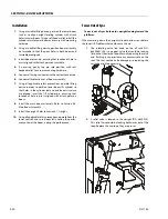
The releveling valve (red knob on the oil tank P/N:
4640866), this is a poppet valve that could be leaking
fluid out of the closed loop. Manually opening the valve
and flushing it can eliminate any contaminate on the
seat. The seat could also be damaged, so replacing the
cartridge might be necessary.
2.
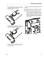
A relief valve is located in the upright (P/N: 4640929).
This relief valve could be leaking backwards out of the
loop. Replace the cartridge. They are pre-set.
Summary of Contents for 740AJ
Page 2: ......
Page 55: ...SECTION 3 CHASSIS TURNTABLE 3121160 3 3 This page left blank intentionally...
Page 116: ...SECTION 3 CHASSIS TURNTABLE 3 64 3121160 Figure 3 44 Swing Hub Prior to SN 0300074383...
Page 203: ...SECTION 3 CHASSIS TURNTABLE 3121160 3 151 Figure 3 77 EFI Component Location...
Page 206: ...SECTION 3 CHASSIS TURNTABLE 3 154 3121160 Figure 3 78 ECM EPM Identification ECM EPM...
Page 224: ...SECTION 3 CHASSIS TURNTABLE 3 172 3121160 Figure 3 83 Deutz EMR 2 Troubleshooting Flow Chart...
Page 228: ...SECTION 3 CHASSIS TURNTABLE 3 176 3121160 Figure 3 87 EMR 2 Engine Plug Pin Identification...
Page 229: ...SECTION 3 CHASSIS TURNTABLE 3121160 3 177 Figure 3 88 EMR 2 Vehicle Plug Pin Identification...
Page 230: ...SECTION 3 CHASSIS TURNTABLE 3 178 3121160 Figure 3 89 EMR2 Fault Codes Sheet 1 of 5...
Page 231: ...SECTION 3 CHASSIS TURNTABLE 3121160 3 179 Figure 3 90 EMR2 Fault Codes Sheet 2 of 5...
Page 232: ...SECTION 3 CHASSIS TURNTABLE 3 180 3121160 Figure 3 91 EMR2 Fault Codes Sheet 3 of 5...
Page 233: ...SECTION 3 CHASSIS TURNTABLE 3121160 3 181 Figure 3 92 EMR2 Fault Codes Sheet 4 of 5...
Page 234: ...SECTION 3 CHASSIS TURNTABLE 3 182 3121160 Figure 3 93 EMR2 Fault Codes Sheet 5 of 5...
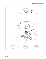
Page 303: ...SECTION 4 BOOM PLATFORM 3121160 4 31 Figure 4 20 Rotator Assembly HELAC...
Page 460: ...SECTION 5 BASIC HYDRAULIC INFORMATION AND SCHEMATICS 5 116 3121160 NOTES...
Page 467: ...SECTION 6 JLG CONTROL SYSTEM 3121160 6 7 Figure 6 2 ADE Block Diagram...
Page 534: ...SECTION 6 JLG CONTROL SYSTEM 6 74 3121160 NOTES...
Page 580: ...SECTION 7 BASIC ELECTRICAL INFORMATION SCHEMATICS 7 46 3121160 NOTES...
Page 581: ......

