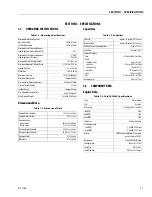
SECTION 1 - SPECIFICATIONS
1-6
3121160
1.5
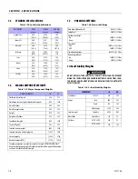
CYLINDER SPECIFICATIONS
1.6
MAJOR COMPONENT WEIGHTS
1.7
PRESSURE SETTINGS
Critical Stability Weights
DO NOT REPLACE ITEMS CRITICAL TO STABILITY WITH ITEMS OF DIFFERENT
WEIGHT OR SPECIFICATION (FOR EXAMPLE: BATTERIES, FILLED TIRES, COUN-
TER WEIGHT, ENGINE, AND PLATFORM) DO NOT MODIFY UNIT IN ANY WAY TO
EFFECT STABILITY.
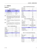
Table 1-26. Cylinder Specifications
DESCRIPTION
BORE
in. (mm.)
STROKE
in. (mm.)
ROD DIA.
in. (mm.)
Upright Level
8.00
(203.6)
42.00
(1066.8)
3.50
(88.9)
Tower Lift
8.00
(203.6)
49.4
(1254.3)
3.00
(76.2)
Main Lift
8.00
(203.2)
28.75
(730.3)
4.00
(101.6)
Telescope
3.50
(88.9)
206.5
(5245.1)
2.74
(70)
Steer 3.00
(76.2)
10.75
(273.1)
1.50
(38.1)
Master
3.50
(88.9)
18.50
(469.9)
1.50
(38.1)
Slave
3.50
(88.9)
17.50
(444.5)
1.50
(38.1)
Lift (Jib)
3.00
(76.2)
25.50
(647.7)
1.50
(38.1)
Table 1-27. Major Component Weights
MAJOR COMPONENTS
LB.
KG.
Platform & Control Console
250
113
Main Boom (Inc. Slave Cylinder Rotator, And Support)
3185
1445
Main Lift Cylinder
445
202
Main Telescope Cylinder
459
218
Upright 1175
535
Upright Level Cylinder
585
265
Tower Boom Complete
3450
1565
Tower Lift Cylinder
544
247
Turntable Counterweight
4805
2180
Turntable Complete (Including Engine)
11025
5001
Chassis Complete
12620
5724
Machine Complete (GVW)
33100
15020
The above components are separate assemblies. Example: “TURNTABLE COMPLETE”
does not include booms, upright, lift cylinders or platform. The weights of these compo-
nents must be added for the total weight.
Table 1-28. Pressure Settings
Main Boom Lift Down Relief
1400 PSI. (97 Bar)
Swing Relief
1400 PSI. (97 Bar)
Platform Level Relief:
Up
Down
2800 PSI. (193 Bar)
1800 PSI. (124 Bar)
Steer Relief
2WS
4WS
1800 PSI. (124.11Bar)
2600 PSI. (179 Bar)
Tower Boom Telescope
2200 PSI. (151.7 Bar)
Articulating Jib Boom
Up
Down
2500 PSI. (172 Bar)
1200 PSI. (83 Bar)
Table 1-29. Critical Stability Weights
COMPONENTS
LB.
KG.
Tire & Wheel
18 X 19.5
675
305
Engine
Ford
600
209
Deutz
534
242
GM w/pumps
1030
468
Counterweight
Turntable
4805
2180
Wheel Hubs
Front & Rear
218
99
Platform
6 FT. (1.83 M)
205
93
8 FT. (2.44 M)
230
105
Summary of Contents for 740AJ
Page 2: ......
Page 55: ...SECTION 3 CHASSIS TURNTABLE 3121160 3 3 This page left blank intentionally...
Page 116: ...SECTION 3 CHASSIS TURNTABLE 3 64 3121160 Figure 3 44 Swing Hub Prior to SN 0300074383...
Page 203: ...SECTION 3 CHASSIS TURNTABLE 3121160 3 151 Figure 3 77 EFI Component Location...
Page 206: ...SECTION 3 CHASSIS TURNTABLE 3 154 3121160 Figure 3 78 ECM EPM Identification ECM EPM...
Page 224: ...SECTION 3 CHASSIS TURNTABLE 3 172 3121160 Figure 3 83 Deutz EMR 2 Troubleshooting Flow Chart...
Page 228: ...SECTION 3 CHASSIS TURNTABLE 3 176 3121160 Figure 3 87 EMR 2 Engine Plug Pin Identification...
Page 229: ...SECTION 3 CHASSIS TURNTABLE 3121160 3 177 Figure 3 88 EMR 2 Vehicle Plug Pin Identification...
Page 230: ...SECTION 3 CHASSIS TURNTABLE 3 178 3121160 Figure 3 89 EMR2 Fault Codes Sheet 1 of 5...
Page 231: ...SECTION 3 CHASSIS TURNTABLE 3121160 3 179 Figure 3 90 EMR2 Fault Codes Sheet 2 of 5...
Page 232: ...SECTION 3 CHASSIS TURNTABLE 3 180 3121160 Figure 3 91 EMR2 Fault Codes Sheet 3 of 5...
Page 233: ...SECTION 3 CHASSIS TURNTABLE 3121160 3 181 Figure 3 92 EMR2 Fault Codes Sheet 4 of 5...
Page 234: ...SECTION 3 CHASSIS TURNTABLE 3 182 3121160 Figure 3 93 EMR2 Fault Codes Sheet 5 of 5...
Page 303: ...SECTION 4 BOOM PLATFORM 3121160 4 31 Figure 4 20 Rotator Assembly HELAC...
Page 460: ...SECTION 5 BASIC HYDRAULIC INFORMATION AND SCHEMATICS 5 116 3121160 NOTES...
Page 467: ...SECTION 6 JLG CONTROL SYSTEM 3121160 6 7 Figure 6 2 ADE Block Diagram...
Page 534: ...SECTION 6 JLG CONTROL SYSTEM 6 74 3121160 NOTES...
Page 580: ...SECTION 7 BASIC ELECTRICAL INFORMATION SCHEMATICS 7 46 3121160 NOTES...
Page 581: ......

