SECTION 5 - BASIC HYDRAULIC INFOR
M
ATION AND SCHE
M
ATICS
5-70
3121160
5.8
HYDRAULIC PUMP W/HAYES PUMP DRIVE
COUPLING LUBRICATION
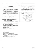
Any time pump or pump drive coupling is removed coat,
pump and drive coupling splines with Lithium Soap Base
Grease (TEXACO CODE 1912 OR EQUIVALENT ) coupling is
greased prior to assembly.
5.9
PRESSURE SETTING PROCEDURES
Cold temperatures have a significant impact on pressure read-
ings. JLG Industries Inc. recommends operating the machine
until the hydraulic system has warmed to normal operating
temperatures prior to checking pressures. JLG Industries Inc.
also recommends the use of a calibrated gauge. Pressure read-
ings are acceptable if they are within ± 5% of specified pres-
sures.
Set Up the Function Pump
BOSCH/REXROTH PUMP
1.
Stand by pressure or load sense pressure
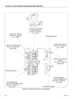
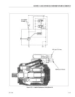
Install a low pressure gauge at port “MP” of the main
valve block. A gauge capable of reading 400 psi (27.5
bar). Remove the wires from the main lift, valve coils on
the main valve block. Start the engine and activate main
lift up or down. Hold the function for 10-15 seconds.
This bleeds the air out of the sense line. The gauge
should be reading 400, +40-0 psi. (27.5, +2.7 -0 bar). To
make an adjustment to this pressure, go to the engine
compartment, locate the variable pump. There are (2)
adjustments at the top of the pump. The stand by
adjustment is at the top. Using a 17 mm wrench, remove
the cover nut. Be careful not to lose the o-ring washer
inside the cover nut. Loosen the jam nut at the set screw
with the 17 mm wrench. Using a 3 mm allen wrench
adjust clockwise to increase, or counterclockwise to
decrease. After adjusting the pressure, tighten the jam
nut and replace the cover nut. Reconnect the wires on
the main lift coils.
2.
High pressure relief
Install a high pressure gauge at the "MP" port of the
main valve block. Activate upper (main) telescope in.
The gauge should read 2600 psi (179 bar). To make an
adjustment to this pressure, go back to the engine com-
partment to the variable pump. The high pressure relief
adjustment is on the lower one of the (2). Repeat the
same procedure as setting the stand by pressure. This is
the maximum relief pressure for all functions governed
by this pump.
SAUER/DANFOSS PUMP
1.
Stand by pressure or load sense pressure
Install a low pressure gauge at port “MP” of the main
valve block. A gauge capable of reading 400 psi (27.5
bar). Remove the wires from the main lift, valve coils on
the main valve block. Start the engine and activate main
lift up or down. Hold the function for 10-15 seconds.
This bleeds the air out of the sense line. The gauge
should be reading 400, +40-0 psi. (27.5, +2.7 -0 bar). To
make an adjustment to this pressure, go to the engine
compartment, locate the function pump. There are (2)
adjustments at the top of the pump. They are located on
the pump compensator which has (4) bolts mounting it
to the pump. The stand by adjustment is at the top. To
adjust this, a 4 mm and 6 mm Allen wrench will be
needed. The adjustment screw is facing the front of the
pump, or towards the engine. First, using 4 m wrench,
loosen the setscrew on the side of compensator (facing
you) which is in line with the adjustment screw. This is
the jam nut screw which holds the main adjustment
from turning. Loosen it 1 turn. Then using the 6 mm
wrench adjust the main adjustment clockwise to
increase or counterclockwise to decrease. The pressure
should read between 400-440 psi.
Summary of Contents for 740AJ
Page 2: ......
Page 55: ...SECTION 3 CHASSIS TURNTABLE 3121160 3 3 This page left blank intentionally...
Page 116: ...SECTION 3 CHASSIS TURNTABLE 3 64 3121160 Figure 3 44 Swing Hub Prior to SN 0300074383...
Page 203: ...SECTION 3 CHASSIS TURNTABLE 3121160 3 151 Figure 3 77 EFI Component Location...
Page 206: ...SECTION 3 CHASSIS TURNTABLE 3 154 3121160 Figure 3 78 ECM EPM Identification ECM EPM...
Page 224: ...SECTION 3 CHASSIS TURNTABLE 3 172 3121160 Figure 3 83 Deutz EMR 2 Troubleshooting Flow Chart...
Page 228: ...SECTION 3 CHASSIS TURNTABLE 3 176 3121160 Figure 3 87 EMR 2 Engine Plug Pin Identification...
Page 229: ...SECTION 3 CHASSIS TURNTABLE 3121160 3 177 Figure 3 88 EMR 2 Vehicle Plug Pin Identification...
Page 230: ...SECTION 3 CHASSIS TURNTABLE 3 178 3121160 Figure 3 89 EMR2 Fault Codes Sheet 1 of 5...
Page 231: ...SECTION 3 CHASSIS TURNTABLE 3121160 3 179 Figure 3 90 EMR2 Fault Codes Sheet 2 of 5...
Page 232: ...SECTION 3 CHASSIS TURNTABLE 3 180 3121160 Figure 3 91 EMR2 Fault Codes Sheet 3 of 5...
Page 233: ...SECTION 3 CHASSIS TURNTABLE 3121160 3 181 Figure 3 92 EMR2 Fault Codes Sheet 4 of 5...
Page 234: ...SECTION 3 CHASSIS TURNTABLE 3 182 3121160 Figure 3 93 EMR2 Fault Codes Sheet 5 of 5...
Page 303: ...SECTION 4 BOOM PLATFORM 3121160 4 31 Figure 4 20 Rotator Assembly HELAC...
Page 460: ...SECTION 5 BASIC HYDRAULIC INFORMATION AND SCHEMATICS 5 116 3121160 NOTES...
Page 467: ...SECTION 6 JLG CONTROL SYSTEM 3121160 6 7 Figure 6 2 ADE Block Diagram...
Page 534: ...SECTION 6 JLG CONTROL SYSTEM 6 74 3121160 NOTES...
Page 580: ...SECTION 7 BASIC ELECTRICAL INFORMATION SCHEMATICS 7 46 3121160 NOTES...
Page 581: ......


