SECTION
4
- BOO
M
& PLATFOR
M
3121160
4-67
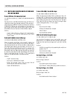
UMS Sensor Not Calibrated Message
8/1 UMS SENSOR NOT CALIBRATED.
If the control system detects a sensor out of range condition or a
not calibrated fault with the UMS angle sensor, the control sys-
tem shall report a fault and disable Tower Lift Down and activate
the ground boom malfunction indicator lamp, upright tilted
lamp and platform alarm continually.
If the control system detects that either angle sensor has not
been calibrated, the ground boom malfunction lamp will flash at
a 3 Hz rate until the system is calibrated or disabled.
Solution:
• Calibrate sensor.
UMS Sensor Faulted
8/1 UMS SENSOR FAULTED
If the system detects that the UMS sensor frequency outside the
100Hz +/- 5Hz range or the duty cycle is outside 50% +/- 21%
range the control system shall report a fault.
Solution:
• Inspect wire harness going to the sensor and UMS module.
• Inspect sensor mounting.
• Replace sensor.
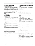
Tower Lift Down Output Short to Ground or Open
Circuit
8/1 TOWER LIFT DOWN OUTPUT SHORT TO GROUND OR OPEN
CIRCUIT.
Short to Ground or open circuit has been detected on the Tower
Lift Down output.
Solution:
• Inspect harness and valve.
Tower Lift Down Output Short to Battery
8/1 TOWER LIFT DOWN OUTPUT SHORT TO BATTERY
Short to battery has been detected on the Tower Lift Down out-
put.
Solution:
• Inspect harness and valve.
Platform Indicator Output Short to Ground or Open
Circuit
8/1 PLATFORM INDICATOR OUTPUT SHORT TO GROUND OR
OPEN CIRCUIT.
Short to Ground or open circuit has been detected on the Plat-
form Indicator output.
Solution:
• Inspect harness.
Platform Indicator Output Short to Battery
8/1 PLATFORM INDICATOR OUTPUT SHORT TO BATTERY.
Short to battery has been detected on the Platform Indicator
output.
Solution:
• Inspect harness.
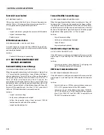
Ground Indicator Output Short to Ground
8/1 GROUND INDICATOR OUTPUT SHORT TO GROUND OR OPEN
CIRCUIT.
Short to Ground or open circuit has been detected on the
Ground Indicator output.
Solution:
• Inspect harness.
Ground Indicator Output Short to Battery
8/1 GROUND INDICATOR OUTPUT SHORT TO BATTERY.
Short to battery has been detected on the Ground Indicator Out-
put.
Solution:
• Inspect harness.
Turntable Sensor Not Calibrated Message
8/1 TURNTABLE SENSOR NOT CALIBRATED.
If the control system detects that the Chassis Tilt sensor is not
calibrated or there is an internal fault with the sensor, the control
system shall disable Tower Lift Down and activate the ground
boom malfunction indicator lamp, upright tilted lamp and plat-
form alarm continually.
If the control system detects that either angle sensor has not
been calibrated, the ground boom malfunction lamp will flash at
a 3 Hz rate until the system is calibrated or disabled.
Solution:
• Calibrate sensor.
Summary of Contents for 740AJ
Page 2: ......
Page 55: ...SECTION 3 CHASSIS TURNTABLE 3121160 3 3 This page left blank intentionally...
Page 116: ...SECTION 3 CHASSIS TURNTABLE 3 64 3121160 Figure 3 44 Swing Hub Prior to SN 0300074383...
Page 203: ...SECTION 3 CHASSIS TURNTABLE 3121160 3 151 Figure 3 77 EFI Component Location...
Page 206: ...SECTION 3 CHASSIS TURNTABLE 3 154 3121160 Figure 3 78 ECM EPM Identification ECM EPM...
Page 224: ...SECTION 3 CHASSIS TURNTABLE 3 172 3121160 Figure 3 83 Deutz EMR 2 Troubleshooting Flow Chart...
Page 228: ...SECTION 3 CHASSIS TURNTABLE 3 176 3121160 Figure 3 87 EMR 2 Engine Plug Pin Identification...
Page 229: ...SECTION 3 CHASSIS TURNTABLE 3121160 3 177 Figure 3 88 EMR 2 Vehicle Plug Pin Identification...
Page 230: ...SECTION 3 CHASSIS TURNTABLE 3 178 3121160 Figure 3 89 EMR2 Fault Codes Sheet 1 of 5...
Page 231: ...SECTION 3 CHASSIS TURNTABLE 3121160 3 179 Figure 3 90 EMR2 Fault Codes Sheet 2 of 5...
Page 232: ...SECTION 3 CHASSIS TURNTABLE 3 180 3121160 Figure 3 91 EMR2 Fault Codes Sheet 3 of 5...
Page 233: ...SECTION 3 CHASSIS TURNTABLE 3121160 3 181 Figure 3 92 EMR2 Fault Codes Sheet 4 of 5...
Page 234: ...SECTION 3 CHASSIS TURNTABLE 3 182 3121160 Figure 3 93 EMR2 Fault Codes Sheet 5 of 5...
Page 303: ...SECTION 4 BOOM PLATFORM 3121160 4 31 Figure 4 20 Rotator Assembly HELAC...
Page 460: ...SECTION 5 BASIC HYDRAULIC INFORMATION AND SCHEMATICS 5 116 3121160 NOTES...
Page 467: ...SECTION 6 JLG CONTROL SYSTEM 3121160 6 7 Figure 6 2 ADE Block Diagram...
Page 534: ...SECTION 6 JLG CONTROL SYSTEM 6 74 3121160 NOTES...
Page 580: ...SECTION 7 BASIC ELECTRICAL INFORMATION SCHEMATICS 7 46 3121160 NOTES...
Page 581: ......


