SECTION 3 - CHASSIS & TURNTABLE
3-160
3121160
3.29 FORD LPG SYSTEM
NOTE:
+20° F (-6.6° C) is the low temperature limit for LP gas, for
both starting and operation. This applies to all LP gas pow-
ered engines.
Description
The LPG system starts at the tank. The liquid propane exits the
tank, flows through the fuel lockoff solenoid, flows through
the regulator (regulator converts the liquid to a vapor), flows
through the megajector, flows through the mixer and into the
engine.
Regulator
The regulator accepts LPG liquid at tank pressure (min = 30 psi;
max = 312 psi [min = 207 kPa; max = 2151 kPa]) and reduces it
to a regulator outlet pressure of 1.5 to 2.5 in. (3.8 to 6.3 cm) of
H
2
O at idle flow (approx. 750 RPM / no load). This regulator
must have engine coolant flowing through it whenever the
engine is running.
Megajector
The megajector is an electronic pressure regulator. This elec-
tronic regulator outputs a specific pressure needed at the
mixer to maintain the desired air to fuel ratio. The megajector
accepts LPG vapor at the regulator outlet pressure (1.5 to
2.5 in. (3.8 to 6.3 cm) of H
2
O) and reduces it to a pressure value
commanded by the EPM. The pressure command is sent by
the EPM over the CAN link via the megajector harness. The
megajector outlet pressure has units of in. of H
2
O. The mega-
jector outlet pressure is defined as the difference between the
megajector outlet gas pressure and the balance line pressure
(usually at or near barometric pressure depending on air
intake restriction). The megajector outlet pressure can vary
between -1.00 to -5.00 in. (-2.5 to -12.7 cm) of H
2
O depending
on the speed and load of the engine. The megajector must be
mounted per the 2.5L 2004 Emission Installation Instructions.
Torque mounting bolts to a maximum of
60 in.lbs. (7 Nm).
Mixer
The mixer accepts LPG vapor at the megajector outlet pres-
sure (-1.00 to -5.00 in. (-2.5 to -12.7 cm) of H
2
O) and mixes it
with clean air. This mixture is then sucked into the engine via
the actuator.
Summary of Contents for 740AJ
Page 2: ......
Page 55: ...SECTION 3 CHASSIS TURNTABLE 3121160 3 3 This page left blank intentionally...
Page 116: ...SECTION 3 CHASSIS TURNTABLE 3 64 3121160 Figure 3 44 Swing Hub Prior to SN 0300074383...
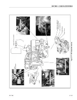
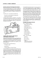
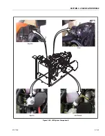
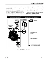
Page 203: ...SECTION 3 CHASSIS TURNTABLE 3121160 3 151 Figure 3 77 EFI Component Location...
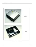
Page 206: ...SECTION 3 CHASSIS TURNTABLE 3 154 3121160 Figure 3 78 ECM EPM Identification ECM EPM...
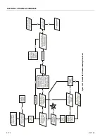
Page 224: ...SECTION 3 CHASSIS TURNTABLE 3 172 3121160 Figure 3 83 Deutz EMR 2 Troubleshooting Flow Chart...
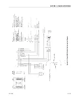
Page 228: ...SECTION 3 CHASSIS TURNTABLE 3 176 3121160 Figure 3 87 EMR 2 Engine Plug Pin Identification...
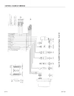
Page 229: ...SECTION 3 CHASSIS TURNTABLE 3121160 3 177 Figure 3 88 EMR 2 Vehicle Plug Pin Identification...
Page 230: ...SECTION 3 CHASSIS TURNTABLE 3 178 3121160 Figure 3 89 EMR2 Fault Codes Sheet 1 of 5...
Page 231: ...SECTION 3 CHASSIS TURNTABLE 3121160 3 179 Figure 3 90 EMR2 Fault Codes Sheet 2 of 5...
Page 232: ...SECTION 3 CHASSIS TURNTABLE 3 180 3121160 Figure 3 91 EMR2 Fault Codes Sheet 3 of 5...
Page 233: ...SECTION 3 CHASSIS TURNTABLE 3121160 3 181 Figure 3 92 EMR2 Fault Codes Sheet 4 of 5...
Page 234: ...SECTION 3 CHASSIS TURNTABLE 3 182 3121160 Figure 3 93 EMR2 Fault Codes Sheet 5 of 5...
Page 303: ...SECTION 4 BOOM PLATFORM 3121160 4 31 Figure 4 20 Rotator Assembly HELAC...
Page 460: ...SECTION 5 BASIC HYDRAULIC INFORMATION AND SCHEMATICS 5 116 3121160 NOTES...
Page 467: ...SECTION 6 JLG CONTROL SYSTEM 3121160 6 7 Figure 6 2 ADE Block Diagram...
Page 534: ...SECTION 6 JLG CONTROL SYSTEM 6 74 3121160 NOTES...
Page 580: ...SECTION 7 BASIC ELECTRICAL INFORMATION SCHEMATICS 7 46 3121160 NOTES...
Page 581: ......

