background image

SECTION 6 - JLG CONTROL SYSTE

M

6-48

3121160

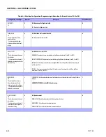
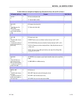
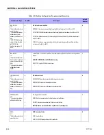
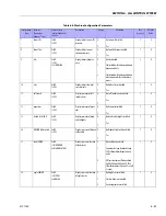
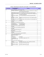
FUEL TANK SIZE:
30

0

1

31 Gallon Tank

52 Gallon Tank

0

ALARM / HORN:
31

0

1

SEPERATE: Separate alarm and horn.

COMBINED: Combination alarm / horn.

0

ALERT / BEACON:
32

0

1

OFF FOR CREEP: Alert beacon will not flash while in Creep.

20 FPS FOR CREEP: Alert beacon will flash at 20 FPS while in Creep.

0

TEMP CUTOUT:
33

0

1

NO: Temp Cutout is Disabled

YES: Temp Cutout is Enabled

0

PLAT LVL OVR CUT:
34

0

1

NO: Platform Level Override will always be functional.

YES: Platform Level Override will only be functional when In Transport.

0

WATER IN FUEL SENSOR:
35*
*This menu item is only vis-
ible if Deutz EMR 4 engine is
selected.
*Only visible under certain 
market selections. 

0

1

NO: Water in Fuel Sensor Disabled.

YES: Water in Fuel Sensor Enabled.

0

4150364-U

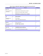
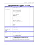
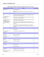
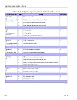
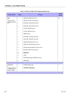
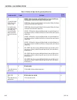
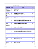
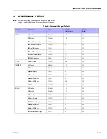
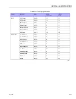
Table 6-5. Machine Configuration Programming Information

Configuration Digit

Number

Description

Default 

Number

Summary of Contents for 740AJ

Page 1: ...Service and Maintenance Manual Model 740AJ Prior to S N 0300185827 P N 3121160 October 24 2017 AS NZS...

Page 2: ......

Page 3: ...re prior to disconnecting or removing any portion of the system Do not use your hand to check for leaks Use a piece of card board or paper to search for leaks Wear gloves to help protect hands from sp...

Page 4: ...ODUCTION A 2 3121160 REVISON LOG Original Issue Revised Revised Revised Revised Revised Revised November 4 2002 September 8 2003 March 10 2006 September 28 2007 June 3 2008 January 8 2013 October 24 2...

Page 5: ...ressure Settings 1 6 Critical Stability Weights 1 6 1 8 Maintenance and Lubrication 1 7 1 9 Draining Oil Build Up From The Propane Regulator Prior to SN 0300134626 1 11 1 10 Propane Fuel Filter Replac...

Page 6: ...tallation 3 8 3 4 Wheel Drive Assembly SN 0300138447 through 0300185827 3 9 Removal 3 9 Installation 3 9 3 5 Drive Hub Prior to SN 0300185827 3 10 Disassembly 3 10 Cleaning and Inspection 3 10 Repair...

Page 7: ...82 One Piece Stator Construction 3 89 3 17 Swing hub SN 0300134353 through 0300185827 3 90 Roll Leak and Brake Testing 3 90 Tightening and Torquing Bolts 3 90 Motor Control Valve Disassembly 3 91 Moto...

Page 8: ...on 3 165 Check Out and Initial Start Up Procedures 3 165 Troubleshooting 3 168 Automatic Choke Adjustment Procedure 3 170 3 31 Deutz EMR 2 3 170 3 32 GM Engine General Maintenance 3 183 Maintenance of...

Page 9: ...Primary Oil Separation 3 210 Secondary Spin On Oil Coalescer Separator 3 210 Spin On Oil Filter 3 210 Minimum Pressure Valve Check Valve Assembly 3 212 Hydraulic Drive System 3 212 Compressor Cooling...

Page 10: ...on 4 20 Tower Out of Sync 4 20 4 9 Articulating Jib Boom 4 23 Removal 4 23 Disassembly 4 23 Inspection 4 23 Assembly 4 24 Installation 4 24 4 10 Limit Switches Adjustment 4 24 Main Boom Horizontal Lim...

Page 11: ...urntable Sensor Not Calibrated Message 4 67 Turntable Sensor Faulted 4 68 EEPROM checksums failure 4 68 4 19 UMS Troubleshooting and Fault Messages ADE Machines 4 68 Backward Stability Concern Message...

Page 12: ...draulic Pump W Hayes Pump Drive Coupling Lubrication 5 70 5 9 Pressure Setting Procedures 5 70 Set Up the Function Pump 5 70 Adjustments Made At The Main Valve Block 5 71 4 Wheel Steer If Equipped 5 7...

Page 13: ...ce Measurement 7 2 Continuity Measurement 7 2 Current Measurement 7 3 7 3 Applying Silicone Dielectric Compound to Electrical Connections 7 3 Installation of Dielectric Grease 7 4 Deutsch HD DT DTM DR...

Page 14: ...nt Prior to SN 0300138447 3 31 3 14 Drive Motor Cross Section 3 32 3 15 Removing the Shaft Seal 3 32 3 16 Loop Flushing Spool 3 33 3 17 Loop Flushing Spool 3 35 3 18 Plugs Fittings and Speed Sensor 3...

Page 15: ...ough 0300185827 Sheet 2 of 2 3 133 3 72 GM Engine Assembly Prior to SN 0300140592 Sheet 1 of 2 3 134 3 73 GM Engine Assembly Prior to SN 0300140592 Sheet 2 of 2 3 135 3 74 GM Engine Assembly SN 030014...

Page 16: ...emoving Sleeve from Housing 4 29 4 19 Actuator Timing 4 30 4 20 Rotator Assembly HELAC 4 31 4 21 Rotator Exploded View SN 0300130881 through 0300185827 4 33 4 22 Rotator Assembly Drawing SN 0300130881...

Page 17: ...nstallation 5 25 5 46 Cylinder Barrel Support 5 26 5 47 Capscrew Removal 5 26 5 48 Cylinder Rod Support 5 26 5 49 Tower Lift Cylinder 5 27 5 50 Tapered Bushing Removal 5 28 5 51 Composite Bearing Inst...

Page 18: ...SN 0300142664 through 0300185827 5 50 5 105 Composite Bearing Installation 5 52 5 106 Rod Seal Installation 5 52 5 107 Cylinder Head Seal Installation 5 52 5 108 Wiper Seal Installation 5 53 5 109 In...

Page 19: ...1 Hand Held Analyzer 6 1 6 2 ADE Block Diagram 6 7 6 3 Analyzer Flow Chart Prior to Version 5 X Software Sheet 1 of 4 6 8 6 4 Analyzer Flow Chart Prior to Version 5 X Software Sheet 2 of 4 6 9 6 5 An...

Page 20: ...Engines Prior to SN 0300099884 Sheet 3 of 6 7 24 7 33 Electrical Schematic Deutz EMR2 GM Engines Prior to SN 0300099884 Sheet 4 of 6 7 25 7 34 Electrical Schematic Deutz EMR2 GM Engines Prior to SN 0...

Page 21: ...P 5046 Specs 1 5 1 26 Cylinder Specifications 1 6 1 27 Major Component Weights 1 6 1 28 Pressure Settings 1 6 1 29 Critical Stability Weights 1 6 1 30 Lubrication Specifications 1 7 2 1 Inspection and...

Page 22: ...6 3 Machine Configuration Programming Information Software Version P5 3 to P6 1 6 31 6 4 Machine Configuration Programming Information Software Version P6 1 to Present 6 36 6 5 Machine Configuration...

Page 23: ...4 42m TurningRadius Inside 11ft 2 13m BoomElevation AboveGrade BelowGrade 80ft 3in 24 46m 13ft 1in 3 99m MachineHeight Stowed 9ft 9 5in 2 98m MachineLength Stowed 36ft 6in 11 13m MachineWidth 8ft 2 44...

Page 24: ...n LowRPM HighRPM 1 90GPH 7 19lph 2 50GPH 9 46lph Battery 1000ColdCrankingAmps 210minutes ReserveCapacity 12VDC Horsepower 64hp 47 7kw 2600RPM fullload Table 1 7 Caterpillar 3044C 3 4 Type FourStrokeCy...

Page 25: ...ccmin DriveHubRatio 87 1 DriveBrake Automaticspringapplied hydraulically releaseddiscbrakes Table 1 12 Swing System Specifications SwingMotorDisplacement 4cu in 66cm3 SwingBrake Automaticspringapplied...

Page 26: ...7 PumpOutput 1 43GPM 5 4lpm 1800psi 124bar PumpDisplacement 0 273cu in 4 48cm3 Motor 24V D C 5 0ExtendedDuty Rotation Counterclockwise Table 1 19 Hydraulic FIlter Specifications ReturnFilter 10Microns...

Page 27: ...obilfluid 424 Specs SAEGrade 10W30 ISOGrade 55 Gravity API 29 0 Density Lb Gal 60 F 7 35 PourPoint Max 46 F 43 C FlashPoint Min 442 F 228 C Viscosity Brookfield cPat 18 C 2700 at40 C 55cSt at100 C 9 3...

Page 28: ...inBoom Inc SlaveCylinderRotator AndSupport 3185 1445 MainLiftCylinder 445 202 MainTelescopeCylinder 459 218 Upright 1175 535 UprightLevelCylinder 585 265 TowerBoomComplete 3450 1565 TowerLiftCylinder...

Page 29: ...wing Bearing Internal Ball Bearing Lube Point s 2 Grease Fittings Capacity A R Lube MPG Interval Every 3 months or 150 hrs of operation Comments Remote Access Figure 1 1 Operator Maintenance and Lubri...

Page 30: ...sition and Check port at 3 o clock position Pour lubricant into fill port until it just starts to flow out of check port 4 Hydraulic Return Filter Interval Change after first 50 hrs and every 6 months...

Page 31: ...vel daily Change in accordance with engine manual 9 Oil Change w Filter Deutz Lube Point s Fill Cap Spin on Element Capacity 11 Quarts 10 5 L Crankcase Lube EO Interval Every Year or 1200 hours of ope...

Page 32: ...or 300 hours of operation 14 Air Filter Lube Point s Replaceable Element Interval Every 6 months or 300 hours of operation or as indicated by the condition indicator 15 Electronic Pressure Regulator L...

Page 33: ...S TO BE LIQUID AND FLOW FREELY FROM THE REGULATOR 1 Move the equipment to a well ventilated area Ensure there are no external ignition sources 2 Start the engine and bring to operating temperature 3 W...

Page 34: ...NG NEW SEAL 1 Install the mounting plate to lock off O ring seal 2 If equipped install the retaining bolt seal 3 Install the housing seal 4 Drop the magnet into the bottom of the filter housing 5 Inst...

Page 35: ...OPANE FUEL SYSTEM PRESSURE WHERE APPLICABLE BEFORE SERVICING THE PROPANE FUEL SYSTEM COMPONENTS To relieve propane fuel system pressure 1 Close the manual shut off valve on the propane fuel tank 2 Sta...

Page 36: ...SECTION 1 SPECIFICATIONS 1 14 3121160 Figure 1 3 Torque Chart Sheet 1 of 5 SAE Fasteners Torq ue To rqu e Torq ue To rqu e Torq ue Torq ue...

Page 37: ...SECTION 1 SPECIFICATIONS 3121160 1 15 Figure 1 4 Torque Chart Sheet 2 of 5 SAE Fasteners Torq ue Tor que Torq ue Torqu e To rqu e...

Page 38: ...SECTION 1 SPECIFICATIONS 1 16 3121160 Figure 1 5 Torque Chart Sheet 3 of 5 SAE Fasteners Cl amp L oa d To rque To rqu e Torq ue Torqu e Tor que Torq ue...

Page 39: ...SECTION 1 SPECIFICATIONS 3121160 1 17 Figure 1 6 Torque Chart Sheet 4 of 5 Metric fasteners To rqu e To rqu e Torq u e To rq ue To rqu e To rq ue...

Page 40: ...SECTION 1 SPECIFICATIONS 1 18 3121160 Figure 1 7 Torque Chart Sheet 5 of 5 Metric Fasteners Torq ue To rqu e Tor qu e To rqu e To rqu e To rq ue...

Page 41: ...e in service for 3 months or 150 hours whichever comes first out of service for a period of more than 3 months or when purchased used The frequency of this inspection must be increased as environ ment...

Page 42: ...y to remove a component on an angle keep in mind that the capacity of an eyebolt or similar bracket lessens as the angle between the sup porting structure and the component becomes less than 90 degree...

Page 43: ...only those having the same specifications of the original or one which is equivalent 2 Unless specific torque requirements are given within the text standard torque values should be used on heat treat...

Page 44: ...rees C is not recommended If it is necessary to start the system in a sub zero environment it will be necessary to heat the oil with a low density 100VAC heater to a minimum temperature of 15 degrees...

Page 45: ...in temperature Cylinder Leakage Test Cylinder oil must be at stabilized ambient temperature before beginning this test Measure drift at cylinder rod with a calibrated dial indicator In an area free of...

Page 46: ...wound bearing are a dry joint and should not be lubricated unless otherwise instructed i e sheave pins c Pins should be inspected to ensure it is free of burrs nicks and scratches which would damage...

Page 47: ...RetractChainorCableSystems 1 2 3 1 2 3 BoomAssembly 1 2 3 4 5 1 2 3 4 5 7 9 14 PlatformAssembly Platform 1 2 Railing 1 1 2 Gate 1 5 1 5 Floor 1 1 2 Rotator 5 9 15 5 9 15 LanyardAnchoragePoint 1 2 10 1...

Page 48: ...ulic ElectricSystem HydraulicPumps 1 2 9 1 2 9 HydraulicCylinders 1 2 7 9 1 2 9 CylinderAttachmentPinsandPinRetainers 1 2 9 1 2 HydraulicHoses Lines andFittings 1 2 9 12 1 2 9 12 HydraulicReservoir Ca...

Page 49: ...stallation 2 Visualinspectionfordamage cracks distortionorexcessivewear 3 Checkforproperadjustment 4 Checkforcrackedorbrokenwelds 5 OperatesProperly 6 Returnstoneutralor off positionwhenreleased 7 Cle...

Page 50: ...COOLER CONSULT JLG SERVICE 180 F 82 C 40 F 40 C 30 F 34 C 20 F 29 C 10 F 23 C 0 F 18 C 10 F 12 C 20 F 7 C 30 F 1 C 40 F 4 C 50 F 10 C 60 F 16 C 70 F 21 C 80 F 27 C 90 F 32 C 100 F 38 C 110 F 43 C 120...

Page 51: ...SECTION 2 GENERAL 3121160 2 11 Figure 2 2 Engine Operating Temperature Specifications Ford 4150548 E...

Page 52: ...COOLER CONSULT JLG SERVICE 180 F 82 C 40 F 40 C 30 F 34 C 20 F 29 C 10 F 23 C 0 F 18 C 10 F 12 C 20 F 7 C 30 F 1 C 40 F 4 C 50 F 10 C 60 F 16 C 70 F 21 C 80 F 27 C 90 F 32 C 100 F 38 C 110 F 43 C 120...

Page 53: ...d rating and size of original Tire tread contact width equal or greater than original Wheel diameter width and offset dimensions equal to the original Approved for the application by the tire manufact...

Page 54: ...BE ABLE TO CONTROL MACHINE AT ALL TIMES ON HIGHWAY TOWING NOT PERMITTED FAILURE TO FOLLOW INSTRUCTIONS COULD CAUSE SERIOUS INJURY OR DEATH MAXIMUM TOWING SPEED 5 M P H 8 K M H MAXIMUM TOWING GRADE 25...

Page 55: ...SECTION 3 CHASSIS TURNTABLE 3121160 3 3 This page left blank intentionally...

Page 56: ...SECTION 3 CHASSIS TURNTABLE 3 4 3121160 1 Figure 3 2 Axle and Steering Installation Sheet 1 of 2 0258286 C...

Page 57: ...15 Washer 16 TieRod 17 SpindleWeldment LeftSide 18 KingPin 19 Bolt 20 SteerPin 21 Bolt 22 Washer 23 WearShim 24 WearShim 25 WearShim 26 Washer 27 Washer 28 Bushing 29 Washer 30 StopPlate 31 Shim 32 S...

Page 58: ...SECTION 3 CHASSIS TURNTABLE 3 6 3121160 1 1 DriveHub 2 DriveBrake 3 DriveMotor 4 SteerCylinders 5 FlowDividerValve2WD 6 FlowDividerValve4WD Figure 3 4 Chassis Component Location...

Page 59: ...URNTABLE 3121160 3 7 1 1 Engine 2 PistonPump 3 GearPump 4 MainControlValve 5 AuxiliaryPowerPump 6 SwingDrive 7 ReturnFilterAssembly 8 HydraulicOilTank 9 FuelTank 10 RotoryCoupling Figure 3 5 Turntable...

Page 60: ...drive brake and drive motor assembly weighs approximately 275 lbs 125 kg 4 Use a supporting device capable of handling the weight of the drive hub drive brake and drive motor and unbolt the drive hub...

Page 61: ...hydraulic lines running to the drive motor Cap or plug all openings to ensure no dirt enters the hydraulic system NOTE The drive hub and drive motor assembly weighs approxi mately 280 lbs 128 kg 4 Us...

Page 62: ...lace bearings as a complete set ensuring that they remain covered until use 3 Inspect bearing mounting surfaces on spindle hub input shaft and carrier Replace components as neces sary 4 Inspect all ge...

Page 63: ...and inspect all parts in accordance with Cleaning and Inspection procedures Replace parts as necessary h Apply a coat of grease or petroleum jelly to cluster gear bore i Place sixteen needle rollers...

Page 64: ...NG REMOVAL AND INSTALLATION a Carefully remove retaining ring 33 from counter bore in the spindle 1 and discard retaining ring b Remove two spacers 31 and spring 32 from input shaft c Clean and inspec...

Page 65: ...l end of hub 3 Press new seal 2 into hub counter bore with flat metal side facing in Use a flat object to ensure that seal is pressed evenly and is flush with hub face 4 Lower hub onto spindle 1 with...

Page 66: ...rnal gear 12 onto end of spindle 9 Install thrust washers and thrust bearing 39 40 on the portion of the spindle which extends into the internal gear 10 Install retaining ring 34 into input shaft reta...

Page 67: ...ted just under carrier on upper two gears 16 With shoulder side of ring gear 21 facing down place ring gear over into mesh with large gears Ensure punch marks remain in correct location during ring ge...

Page 68: ...um jelly or grease to hold o ring in place 22 Place cover assembly over ring gear with oil level check plug in cover located approximately 90 degrees from oil fill plug in hub 23 Locate four shoulder...

Page 69: ...Gear 13 Carrier 14 ThrustWasher 15 NeedleRoller 16 Spacer 17 PistonShaft 18 ClusterGear 19 RollPin 20 NotUsed 21 ClusterGear 22 O ring 23 Cover 24 CoverCap 25 Bolt 26 DisconnectCap 27 DisconnectRod 28...

Page 70: ...t is flush with bearing shoulder Note direction of seal 3 Press bearing 18 into position until it bottoms out on borestep NOTE Cover plate 16 must be supported as indicated in Figure 3 9 4 Install ret...

Page 71: ...urePlate 4 CaseSeal 5 O ring 6 BackupRing 7 Piston 8 O ring 9 BackupRing 10 Shaft 11 StatorDisc 12 RotorDisc 13 ReturnPlate 14 Springs 15 DowelPin 16 CoverPlate 17 OilSeal 18 Bearing 19 RetainingRing...

Page 72: ...iscplatesworn Thethicknessofthediscstacksetsthetorquelevel Athinstackreducestorque Checkdiscthickness Springsbrokenorhavetakenapermanentset Brokenorsetspringscancausereducedtorque a rareoccurrence Che...

Page 73: ...ge or fatigue 5 Check ball bearing 10 for axial float or wear 6 Examine o ring seals 15 17 and backing rings 16 18 for damage Assembly 1 Lightly lubricate rotary shaft seal 12 and assemble to housing...

Page 74: ...g 3 FrictionPlate 4 PressurePlate 5 Gasket 6 OuterPlate 7 Gasket 8 Cylinder 9 Piston 10 BallBearing 11 RetainingRing 12 ShaftSeal 13 Capscrew 14 Lockwasher 15 O ring 16 BackupRing 17 O ring 18 BackupR...

Page 75: ...Same sealing kit like shown above only seal material changed to Viton Drive shaft Bearing set miscellaneous parts Rotary group complete 9 pistons cylinder sub assembly valve plate cw or ccw correspon...

Page 76: ...SIS TURNTABLE 3 24 3121160 Replacing the Drive Shaft Seal 1 Remove the snap ring 2 Change the shaft seal and check its sliding surface drive shaft and housing grease the sealing ring Figure 3 11 Drive...

Page 77: ...g ring in the correct position in the pump housing 5 Assemble the snap ring 6 Assemble the snap ring in the correct position Disassembly and Assembly 1 Disassemble the pilot valve 2 Mark the position...

Page 78: ...ent shim 7 Unscrew the cap nut and remove it 8 Loosen the retaining nut of the stopper max flow and remove it 9 Turn in the stopper max flow to get swivel angle zero 10 Disassemble the rotary group in...

Page 79: ...sassemble the control piston while moving the swash plate 15 The swash plate must be lifted a little bit to disassemble the piston rod 16 Disassembly of the swash plate 17 Remove the spring 18 Remove...

Page 80: ...e the O ring Lifting of the valve plate isn t shown 24 A usual commercial bearing puller is used to disassem ble the external bearing ring of the taper roller bearing inside the port plate Take care n...

Page 81: ...direction NOTE Spare parts exist as cw and ccw valve plates 4 Pumps counterclockwise driven must have a position of the valve plate 4 degrees de centered in ccw position 5 Assembly of the port plate...

Page 82: ...SECTION 3 CHASSIS TURNTABLE 3 30 3121160 NOTE Differential volume if you are rotating the threaded pin each rota tion is appr 3 1 cm3 Figure 3 12 Flow Control Pilot Valves...

Page 83: ...n you will be able to reduce the flow from Vg max to 50 of Vg max Drive Motor Adjustment Procedure Prior to SN 0300138447 1 Remove the cap nut from adjustment screw 2 Loosen jam nut on the adjustment...

Page 84: ...fully pry out the shaft seal 3 To avoid damaging the shaft during removal install a large sheet metal screw into the chuck of a slide ham mer Drive the screw into the seal surface and use the slide ha...

Page 85: ...Also check springs and poppet for wear INSTALLATION 1 Install orifice poppet 13 2 Install shift spool 12 3 Install spring retaining washers onto springs 10 and 11 4 Carefully install centering spring...

Page 86: ...oirandoil supplytothepump Insufficientamountofhydraulicfluidwillnotmeetthecooling demandsofthesystem Fillthereservoirtotheproperlevel Inspecttheheatexchanger ifso equipped Iftheheatexchangerfails orbe...

Page 87: ...speed sensor lock nut 14 if equipped Then remove the speed sensor using a Vi in hex wrench Units without speed sensor have an o ring plug 15 installed in that location remove it with a Va in internal...

Page 88: ...t two digits of the valve plate part number are stamped on its surface 16 Remove and discard the o rings 27 28 17 Remove the rear shaft bearing 29 from the endcap with a bearing puller The bearing may...

Page 89: ...seal 34 Discard the seal To avoid damaging the shaft during seal removal Install a large sheet metal screw into the chuck of a slide ham mer Drive the screw into the seal surface and use the slide ham...

Page 90: ...down pins 48 and retaining ring 49 from the cylinder block NOTE Most repairs do not require block spring removal Perform this procedure only if you suspect problems with the block spring RISK OF PERS...

Page 91: ...ay indicate excessive heat do not reuse SLIPPERS Inspect the running surface of the slippers Replace any piston assemblies with scored or excessively rounded slipper edges Measure the slipper foot thi...

Page 92: ...ge or excessive wear Some material transfer may appear on these surfaces and is acceptable pro viding the surface condition meets specifications shown Mea sure the swashplate thickness from the journa...

Page 93: ...cket for damage or excessive wear Replace if necessary LOOP FLUSHING SPOOL Inspect the loop flushing spool Check for cracks or damage Replace if necessary Assembly 1 Install new O ring 1 and piston se...

Page 94: ...e retainer seats on the ball guide If you re reusing the pistons install them to the original block bores Lubricate the pistons slippers retainer and ball guide before assembly Set the cylinder kit as...

Page 95: ...19 onto the shaft Install with the slippers facing the swashplate Rock the shaft to align the block splines and slide the cylinder kit into place Orient the motor with the shaft pointing downward and...

Page 96: ...ndcap 25 onto the housing with the end cap screws 26 Check to ensure the endcap will prop erly seat onto the housing without interference Improper assembly of the internal components may prevent the e...

Page 97: ...Install seal sup port washer 28 and snap ring 29 19 Install remaining plugs and fittings to the housing Refer to the drawing below for wrench sizes and installation torques 29 28 27 27 ShaftSeal 28 Se...

Page 98: ...Pour filtered oil directly into the upper most case drain port 4 To ensure the pump and motor stay filled with oil install case drain lines into the upper most case drain ports 5 Install a 0 to 500 ps...

Page 99: ...sting bolts for looseness 1 Check the frame to bearing attach bolts as follows a Elevate the fully extended main boom to horizontal See Figure 3 38 b At the positions indicated on Figure 3 39 try to i...

Page 100: ...SECTION 3 CHASSIS TURNTABLE 3 48 3121160 Figure 3 37 Swing Bearing Tolerance Boom Placement Sheet 1 of 2...

Page 101: ...SECTION 3 CHASSIS TURNTABLE 3121160 3 49 Figure 3 38 Swing Bearing Tolerance Boom Placement Sheet 2 of 2...

Page 102: ...ng Replacement REMOVAL 1 From Ground Control station operate the boom ade quately to provide access to frame opening to rotary coupling NEVER WORK BENEATH THE BOOM WITHOUT FIRST ENGAGING BOOM SAFETY P...

Page 103: ...Bearing Removal 740AJ CG C ROTATION 28 5 72 4 cm Gross Weight 19700 lbs 8936 kg Upper Works above Turntable Bearing Hole in T T L NOTE CG location may vary slightly depending on the exact configuratio...

Page 104: ...with the scribed line on the frame If a new swing bearing is used ensure that the filler plug fitting is at 90 degrees from the fore and aft center line of the frame JLG INDUSTRIES RECOMMENDS THAT AL...

Page 105: ...new bear ing bolts Then apply a light coating of Loctite 271 to the new bearing bolts and install the bolts and washers through the turntable and inner race of the bearing 8 Following the Torque Seque...

Page 106: ...SECTION 3 CHASSIS TURNTABLE 3 54 3121160 1 1 Bolt 2 JamNut 3 Shim 4 ShoulderScrew 5 Capscrew 6 Washer 7 SwingMotorandDriveAssembly Figure 3 43 Swing Drive Installation...

Page 107: ...ea 3 12 SWING HUB INSTALLATION Ensure mounting plate and mounting location of the base plate are clean and painted with a uniform coating of mini mum thickness no runs drips etc Procedure For Setting...

Page 108: ...to SN 0300134352 Pre torque to 30 ft lbs 42 Nm for SN 0300134353 through 0300185827 5 Tighten setscrew until pinion is completely snug against shim and bearing then back off setscrew 6 Apply JLG Threa...

Page 109: ...ing Cone 1D will remain on the Output Shaft 1A The Seal 1B will be automatically removed during this procedure NOTE If bearing replacement is necessary the Bearing Cups can be removed with a slide ham...

Page 110: ...s should be a slip fit and the Thrust Spaces should rotate in this location 5 Place Carrier Assembly 3 on a flat surface with the large gears 3F up and positioned as shown Find the punch marked tooth...

Page 111: ...Gear 8 locates on the shoulder of the Thrust Spacer 9 This is to be a slip fit and operate freely 9 Thrust Washer 10 is installed onto the Input Gear 8 and should locate on the gear teeth shoulder 10...

Page 112: ...ue Shoulder Bolts 13 to 23 27 ft lbs and regular Grade 8 Bolts 12 to 23 27 ft lbs 16 The unit must be completely filled with EP 90 lubricant before operation Hub Shaft Sub Assembly 1 Press Bearing Con...

Page 113: ...alled smooth face UP and located just flush with the counterbore face 6 The Bearing Cone 1F is an interference fit and has to be pressed or tapped on 7 Pipe Plugs 1J 1K should be checked and or instal...

Page 114: ...internal end of the Output Shaft 1A twice with a piece of soft metal rod This will release the preload which was on the Bearings 12 If the assembly is not going to be used right away it should be oil...

Page 115: ...have slots and tangs should be located inside boss relief 6 While keeping Thrust Washers in place slide Cluster Gear into Carrier with the larger gear on the side with the small pin hole 7 Line up Clu...

Page 116: ...SECTION 3 CHASSIS TURNTABLE 3 64 3121160 Figure 3 44 Swing Hub Prior to SN 0300074383...

Page 117: ...ing this procedure NOTE If bearing replacement is necessary the bearing cups can be removed with a slide hammer puller driven out with a punch 11 To remove the cluster gears 3F from the carrier 3A dri...

Page 118: ...ears Be sure that punch marks remain in correct location during ring gear installation The side of the ring gear with an x stamped on it should be up 7 While holding ring gear 4 and cluster gears 3F i...

Page 119: ...GES OF THE COUNTERBORE WHILE SEATING THIS O RING 12 The cover 6 is now installed on this assembly Taking care to correctly align pipe plug hole 20 with those in the hub 1J usually 90 to one another Lo...

Page 120: ...ub Shaft Sub Assembly 1 Press bearing cone 1D onto shaft 1A 2 Press bearing cup 1C into hub 1G taking care to insure cup start square with the bore of the hub 3 Invert hub 1G and press bearing cup 1E...

Page 121: ...around the output shaft 1A and locates on bearing cone 1F 9 Retaining ring 1I installed into groove provided in the output shaft 1A This retaining ring 1I should never be reused in a repair or rebuild...

Page 122: ...haft sub assembly items 1A through 1J If this assembly is not going to be used right away it should be oiled and covered to help prevent rusting Carrier Sub Assembly 1 Apply a coat of grease or petrol...

Page 123: ...be located inside boss relief 6 While keeping thrust washers in place slide cluster gear into carrier with the larger gear on the side with the small pin hole 7 Line up cluster gear and thrust washer...

Page 124: ...SECTION 3 CHASSIS TURNTABLE 3 72 3121160 Figure 3 45 Swing Drive Hub Fairfield SN 0300074383 through 0300134352...

Page 125: ...5 Check ball bearing 10 for axial float or wear 6 Examine o ring seals 15 17 and backing rings 16 18 for damage Assembly 1 Lightly lubricate rotary shaft seal 12 and assemble to housing 2 taking care...

Page 126: ...ing 3 FrictionPlate 4 PressurePlate 5 Gasket 6 OuterPlate 7 Gasket 8 Cylinder 9 Piston 10 BallBearing 11 RetainingRing 12 ShaftSeal 13 Capscrew 14 Lockwasher 15 O ring 16 BackupRing 17 O ring 18 Backu...

Page 127: ...the Torq link components from end cover 2 to housing 18 to facilitate reassembly orientation where required Loosen two shuttle or relief valve plugs 21 for disassembly later if included in end cover 3...

Page 128: ...Ring 7 Manifold 8 RotorSet 8A Rotor 8B StatororStatorVane 8C Vane 8D StatorHalf 9 WearPlate 10 DriveLink 12 CouplingShaft 13 Bearing Bushing Inner 14 ThrustWasher 15 ThrustBearing 16 Seal 17 BackupWas...

Page 129: ...cover for cracks and the bolt head recesses for good bolt head sealing surfaces Replace end cover as necessary NOTE A polished pattern not scratches on the cover from rota tion of the commutator 5 is...

Page 130: ...acement the complete rotor set must be replaced as it is a matched set Inspect the warplane for cracks brinelling or scoring Discard seal ring 4 that is between the rotor set and wearplate NOTE The ro...

Page 131: ...card seal ring 4 from housing 18 13 Remove thrust bearing 11 from top of coupling shaft 12 Inspect for wear brinelling corrosion and a full complement of retained rollers 14 Check exposed portion of c...

Page 132: ...Inspect for wear brinelling corrosion and a full comple ment of retained rollers 18 Remove seal 16 and back up washer 17 from Small Frame housing 18 Discard both 19 Remove housing 18 from vise invert...

Page 133: ...s not pass inspec tion must be replaced If the housing has passed this inspection the disassembly of the Torqlink is com pleted NOTE The depth or location of bearing bushing 13 in relation to the hous...

Page 134: ...components were removed for replacement thoroughly coat and pack a new outer bearing bushing 19 with clean corrosion resistant grease recommended in the material section Press the new bearing bushing...

Page 135: ...h to 0 03 in 0 76 mm below the housing wear plate contact face Use the opposite end of the bearing man drel that was used to press in the outer bearing bushing 19 3 Press a new dirt and water seal 20...

Page 136: ...R 25 WHEN DISASSEMBLED MUST BE ASSEMBLED WITH A NEW BACKUP WASHER 17 NEW BACKUP WASHER 25 AND NEW SEAL 16 6 Assemble thrust washer 14 then thrust bearing 15 that was removed from the Torqlink NOTE Tor...

Page 137: ...al ring groove NOTE One or two alignment studs screwed finger tight into hous ing 18 bolt holes approximately 180 degrees apart will facilitate the assembly and alignment of components as required in...

Page 138: ...original rotor drive link spline contact A rotor set without a counterbore and that was not etched before disassembly can be reinstalled using the drive link spline pattern on the rotor splines if ap...

Page 139: ...to manifold 7 with seal ring side up 19 If shuttle valve components items 21 were removed from the end cover 2 turn a plug 21 loosely into one end of the valve cavity in the end cover A 3 16 in Allen...

Page 140: ...omponents into place with a final torque of 22 26 ft lbs 45 55 ft lbs 61 75 N m for the seven 3 8 24 threaded bolts NOTE The special bolts required for use with the relief or shuttle valve 24 end cove...

Page 141: ...0 splines NOTE If the manifold side of the rotor was etched during Torqlink disassembly this side should be up If the rotor is not etched and does not have a counterbore use the drive link spline cont...

Page 142: ...l after the unit has been pressurized and allowed to equalize Leaks will most likely occur at the pipe plugs the main seal or wherever o rings or gaskets are located The exact location of a leak can u...

Page 143: ...tube with a wrench 4 Using a wrench loosen jam nuts on Elbow Fittings 30 and remove fittings from Brake 6 and Motor Control Valve 32 5 Remove O ring Plugs 23 from Motor Control Valve 32 6 Remove Moto...

Page 144: ...ring 26 from between Motor 31 and Brake Housing 6 4 Remove the Springs 8L from the piston 5 Apply less than 50 psi 3 45 bar air to the brake port to remove Brake Piston 8A THE PISTON MAY MOVE QUICKLY...

Page 145: ...between Brake Hous ing 6 and Carrier Subassembly 6 Remove Ring Gear 4 from Housing 1G 7 Remove O ring 5 from between Ring Gear 4 and Housing 1G 8 Remove Carrier Sub Assembly 9 Remove Thrust Washer 11...

Page 146: ...Shaft 1A end press the Output Shaft 1A out of the Housing 1G NOTE The Lip Seal 1B will be pressed out of the Housing 1G by the Bearing Cone 1D during this step 4 Remove the Bearing Cone 1E from the H...

Page 147: ...e Planet Shaft is removed 2 Remove the Planet Shaft 3E from the Carrier 3A Use a small punch to remove the Roll Pin 3D from the Planet Shaft 3E 3 Slide the Planet Gear 3F the two Thrust Washers 3B out...

Page 148: ...lbs 31 to 32 Nm Carrier Assembly NOTE Refer to Figure 3 52 1 Apply a liberal Coat of grease to the bore of Cluster Gear 3F This will enable the Needle Rollers 3C to be held in place during assembly 2...

Page 149: ...F Be sure that cluster gear timing marks punch marks remain in correct location during Ring Gear 4 installation The side of the Ring Gear 4 with an X or punch mark stamped on it should be up 8 While h...

Page 150: ...o 80 100 ft lbs 108 136 Nm Motor Control Valve Assembly NOTE Refer to Figure 3 48 1 Lay assembly down with motor ports facing up Remove the two plastic plugs in the motor ports being careful not to lo...

Page 151: ...earing 1D Bearing 1G Housing 1H Thrust Washer 1I Retaining Ring 1J Pipe Plug 2 Internal Gear 3 Carrier Assembly 4 Ring Gear 5 0 Ring 5A O Ring 6 Brake Housing 8 Sun Gear 11 Thrust washer 12 Bolt 13 Do...

Page 152: ...hrust Washer 22 Lock washer 23 Pipe Plug 26 0 Ring 28 Lifting lug 29 Bolt 30 Elbow 35 Tube 101 Bolt 102 End Cover 103 Commutator Seal 104 Ring Seal 105 Commutator and Ring Assy 106 Ring 107 Manifold 1...

Page 153: ...t mark down and across the Torqmo tor components from end cover 2 to housing 18 to facilitate reassembly orientation where required Loosen two shuttle or relief valve plugs 21 for disassembly later if...

Page 154: ...ifold 8 Rotor Set 8A Rotor 8B Stator or Stator Vane 8D Stator Half 9 Wear Plate 10 Drive Link 11 Not Used 12 Coupling Shaft 13 Bearing Bushing Inner 14 Thrust Washer 15 Thrust Bearing 16 Seal 17 Backu...

Page 155: ...are free of contamination Inspect end cover for cracks and the bolt head recesses for good bolt head sealing surfaces Replace end cover as necessary NOTE A polished pattern not scratches on the cover...

Page 156: ...acement the complete rotor set must be replaced as it is a matched set Inspect the warplane for cracks brinelling or scoring Discard seal ring 4 that is between the rotor set and wear plate NOTE The r...

Page 157: ...bearing 11 from top of coupling shaft 12 Inspect for wear brinelling corrosion and a full complement of retained rollers 14 Check exposed portion of coupling shaft 12 to be sure you have removed all s...

Page 158: ...for wear brinelling corrosion and a full comple ment of retained rollers 18 Remove seal 16 and back up washer 17 from Small Frame housing 18 Discard both 19 Remove housing 18 from vise invert it and...

Page 159: ...s not pass inspec tion must be replaced If the housing has passed this inspection the disassembly of the Torqmotor is com pleted NOTE The depth or location of bearing bushing 13 in relation to the hou...

Page 160: ...components were removed for replacement thoroughly coat and pack a new outer bearing bushing 19 with clean corrosion resistant grease recommended in the material section Press the new bearing bushing...

Page 161: ...h to 0 03 in 0 76 mm below the housing wear plate contact face Use the opposite end of the bearing man drel that was used to press in the outer bearing bush ing 19 3 Press a new dirt and water seal 20...

Page 162: ...ing 18 if they were not assembled in procedure 2 ORIGINAL DESIGN LARGE FRAME TF TG TORQMOTORS THAT DO NOT HAVE BACKUP WASHER 25 WHEN DISASSEMBLED MUST BE ASSEMBLED WITH A NEW BACKUP WASHER 17 NEW BACK...

Page 163: ...NOTE The coupling shaft 12 will be flush or just below the hous ing wear plate surface on Torqmotors when properly seated The coupling shaft must rotate smoothly on the thrust bearing package 9 Apply...

Page 164: ...t stator 8B 13 Install the assembled rotor set 8 onto wear plate 9 with rotor 8A counterbore and seal ring side down and the splines into mesh with the drive link splines NOTE It may be necessary to t...

Page 165: ...inside diameter The polished impression left on the manifold by the rotor set is another indication of which surface must contact the rotor set 15 Assemble the manifold 7 over the alignment studs and...

Page 166: ...end cover 2 and assemble end cover over the alignment studs and onto the commutator set If the end cover has only 5 bolt holes be sure the cover holes are aligned with the 5 threaded holes in housing...

Page 167: ...lts required for use with the relief or shuttle valve 24 end cover assembly 2 are longer than the bolts required with standard and cover assembly Refer to the individual service parts lists or parts l...

Page 168: ...0 splines NOTE If the manifold side of the rotor was etched during Torqmo tor disassembly this side should be up If the rotor is not etched and does not have a counterbore use the drive link spline co...

Page 169: ...end 3 Remove center body 1 from housing 3 4 Cut off old seals 2 4 5 5 Assemble lip seals 2 in direction shown in Figure 3 56 Rotary Coupling Seal Installation Prior to SN 0300138447 6 Reassemble o ri...

Page 170: ...SECTION 3 CHASSIS TURNTABLE 3 118 3121160 1 1 CenterBody 2 Seal 3 Housing 4 O ring 5 CapSeal 6 Ring 7 RetainingRing Figure 3 57 Rotary Coupling Cutaway Prior to SN 0300138447...

Page 171: ...SECTION 3 CHASSIS TURNTABLE 3121160 3 119 9 Figure 3 58 Rotary Coupling Port Location 9 Port Prior to SN 0300138447 1660223 C...

Page 172: ...60 1 Loctite 242 2 Bolt 3 Bolt 4 Bolt 5 Bracket 6 RotaryCoupling 7 Spool 8 RetainingRing 9 Plug 10 TorqueLug 11 Ring 12 Seal 13 O ring 14 Bearing 15 CapSeal 16 O ring 17 Case Figure 3 59 Rotary Coupli...

Page 173: ...ring 3 from the same end 4 Remove center body 1 from housing 3 5 Cut off old seals 2 4 5 6 Remove proximity switch 7 Assemble lip seals 2 in direction shown in Figure 3 56 Rotary Coupling Seal Instal...

Page 174: ...URNTABLE 3 122 3121160 1 CenterBody 2 Seal 3 Housing 4 O ring 5 Seal 6 ThrustRing 7 SnapRing 8 ValveBlock AxleOscillation 9 O ring 10 ProximitySwitch Figure 3 61 Rotary Coupling Cutaway SN 0300138447...

Page 175: ...SECTION 3 CHASSIS TURNTABLE 3121160 3 123 4 9 8 3 1 2 4 2 3 8 7 6 7 9 6 5 1 2 7 2 3 6 7 2 1 8 9 7 Figure 3 62 Rotary Coupling Port Location 9 Port SN 0300138447 through 0300185827...

Page 176: ...otaryCoupling 7 Spool 8 RetainingRing 9 Plug 10 TorqueLug 11 Ring 12 Seal 13 O ring 14 Bearing 15 CapSeal 16 O ring 17 Valve 18 CheckValve 19 Case 20 PlungerValve 21 Bolt 22 Nut 23 Washer 24 Bracket 2...

Page 177: ...er 2000 138 3000 206 8 5 3 2 6 1 16 DriveReverse 4500 310 6750 465 6 1 16 DriveForward 4500 310 6750 465 7 2 12 Drain 250 17 375 26 8 1 6 Steer 2000 138 3000 206 8 9 1 6 Steer 2000 138 3000 206 8 Port...

Page 178: ...lly push down on one corner at a time there should be enough travel to cause the switch to trip If the switch does not trip in all three tests the flange nuts have been tightened too far Loosen the X...

Page 179: ...r 8 Pin 9 IdlerShaft 10 MountingGasket 11 ShaftSeal 12 Stator 13 Washer 14 Screw 15 GasketKit 16 NeedleBearing 17 DriveShaft 18 Key 19 RetainingRing 20 Gear 21 HexCap 22 AdjustmentScrew 23 Gasket 24 S...

Page 180: ...SECTION 3 CHASSIS TURNTABLE 3 128 3121160 1 Figure 3 66 Auxiliary Pump Location 1 AuxiliaryPump 2 HydraulicTank...

Page 181: ...1160 3 129 3 23 DEUTZ ENGINE 1 1 RadiatorMounting 2 Fan 3 ExhaustTube 4 AirCleaner 5 GearPump 6 PistonPump 7 PumpAdapterPlate 8 DeutzENgine 9 OilCooler Figure 3 67 Deutz Engine Assembly SN 0300077500...

Page 182: ...10 10 EngineTray 11 Battery 12 FuelTank 13 HitchPin 14 EGRRelay 15 BatteryHold Down 16 RubberPanel 17 FuelFilter Figure 3 68 Deutz Engine Assembly SN 0300077500 through 0300185827 Sheet 2 of 2 RETURN...

Page 183: ...1 FordLRG 425Engine 2 RadiatorMount 3 Battery 4 EngineTray 5 Fan 6 PumpCoupling 7 PistonPump 8 ModuleMount 9 AirCleaner 10 EPMModule 11 GearPump 12 EngineMount 13 Muffler 14 Radiator 15 FuelPump Figu...

Page 184: ...ount 3 Radiator 4 Fan 5 EngineMount 6 CouplingPump 7 PistonPump 8 PumpAssembly 9 AirCleaner 10 Muffler 11 EngineMount Front 12 PressureRegulatorandFilter 13 EngineMount Rear 14 ExhaustPipe Figure 3 70...

Page 185: ...1160 3 133 15 15 EngineTray 16 Battery 17 HitchPin 18 FuelTank 19 FuelPumpMount 20 ECMMount 21 RubberPanel 22 BatteryHold Down 23 FuelFilter 24 FuelPump Figure 3 71 Ford Engine Assembly SN 0300077500...

Page 186: ...1 GMEngine 2 EngineTray 3 Battery 4 Muffler 5 PistonPump 6 GearPump 7 RadiatorMount 8 AirCleaner 9 Radiator 10 RubberPanel 11 Fan 12 BatteryHold Down 13 EngineMount Front 14 EngineMount Rear Figure 3...

Page 187: ...SECTION 3 CHASSIS TURNTABLE 3121160 3 135 15 15 OilFilter 16 FuelTank 17 FuelFilter 18 LPHose 19 IntakeTube Figure 3 73 GM Engine Assembly Prior to SN 0300140592 Sheet 2 of 2...

Page 188: ...atorMount 5 Radiator 6 Fan 7 PistonPump 8 GearPump 9 RubberPanel 10 BatteryHold Down 11 Muffler 12 Relay 13 ControlModule ECU 14 AirCleaner 15 EngineMount Front 16 EngineMount Rear 17 IntakeTube 18 Oi...

Page 189: ...SECTION 3 CHASSIS TURNTABLE 3121160 3 137 13 19 FuelFilterBracket 20 Tube FuelLine 21 LPHose 22 FuelTank 23 FuelFilter Figure 3 75 GM Engine Assembly SN 0300140592 through 0300185827 Sheet 2 of 2...

Page 190: ...es and Cleaning Slip Rings Refer to Figure 3 76 Inspecting Generator Brushes Replacing Brushes and Cleaning Slip Rings INSPECTING BRUSH POSITION Inspect brush alignment with slip rings View alignment...

Page 191: ...eplace 2 7 16 in 1 2 in 11 12 mm New 3 2 3 Brushes must ride completely on slip rings Acceptable Unacceptable Brush Position On Slip Rings Figure 3 76 Inspecting Generator Brushes Replacing Brushes an...

Page 192: ...s andbrushpositiononsliprings Installnewbrushesifnecessary Disconnectleads12and13frombrushes andcheckcontinuityacrossslipringsnominalreadingis26ohms Replacegenerator ifrotorisopen Disconnectstatorweld...

Page 193: ...source of the problem If no matching symptom is available analyze the complaint and develop a plan for diagnostics utilizing the wiring dia grams technical assistance and repair history Intermittent...

Page 194: ...fuel injection pulse and the engine will continue to nun As long as the fault is present the engine can be restarted It will run in the previously established injec tion sequence ENGINE COOLANT TEMPE...

Page 195: ...gineCoolantTemperature ECT SensorHighVoltage 35 IntakeAirTemperature IAT SensorHighVoltage 41 FuelPumpHighVoltage 42 HeatedOxygenSensor HO2S HighVoltage 43 EngineCoolantTemperature ECT SensorLowVoltag...

Page 196: ...LoopMultiplierLow NaturalGas ThisfaultsetsiftheClosedLoopmultiplierexceedsthelimitsofnormaloperation Whenthemulti pliercannotcorrectlymodifythefuelflowwithinitslimits itislimitedat 35 Thisoccurswhenth...

Page 197: ...useadefaultvaluefortheECTsensorintheeventofthisfault 231 MAPHighPressure ThisfaultwillsetwhentheMAPreadingishigherthanitshouldbeforthegivenTPS andRPM When thefaultisset theAdaptiveLearnwillbedisabledf...

Page 198: ...ultoccurs theMILlightwillilluminateandtheengine willshutdown 352 FuelPumpHighSideShortedToPower ThisfaultwillsetiftheEPMdetectsFuelPumphigh sidevoltagegreaterthan4voltswhilethepump shouldbeoffandtheba...

Page 199: ...dmustthereforeenforcetheLowRevLimitandPowerDerate level1 Whentheseare enforcedthemaximumthrottlepositionis50 andthemaximumenginespeedis1600RPM The LowRevLimitisenforcedfortheremainderofthekey oncycle...

Page 200: ...etanytimetheengineRPMexceeds4900for2secondsormorecontinuously When theseconditionsaremet theEPMwillshutoffsparktotheengine Thisistohelppreventengineor equipmentdamage NOTE IfanyotherDTCsarepresent dia...

Page 201: ...5Voltreferenceisabove5 4volts 655 RTI2Loss Severaldifferentthingscanhappenwithinthemicroprocessorthatwillcausethisfault TheEPMwill resetitselfintheeventthisfaultisset andtheMILwillbeonuntilthecodeiscl...

Page 202: ...d to compensate High HO2S voltage indicates a rich mixture which will result in a lean command to compensate A constant voltage below 200 mV for 10 consecutive seconds will set OTC 32 A constant volta...

Page 203: ...SECTION 3 CHASSIS TURNTABLE 3121160 3 151 Figure 3 77 EFI Component Location...

Page 204: ...ms the diagnostic function of the system It can recognize operational problems alert the operator through the Malfunction Indica tor Lamp MIL and store diagnostic trouble codes DTCs DTCs identify the...

Page 205: ...c governor The Engine Module monitors the voltage on the signal line and calculates throttle position As the throt tle valve angle is changed the TP sensor signal also changes At a closed throttle pos...

Page 206: ...SECTION 3 CHASSIS TURNTABLE 3 154 3121160 Figure 3 78 ECM EPM Identification ECM EPM...

Page 207: ...has been handled while sliding across a seat while sitting down from a standing position or while walk ing a distance touch a known good ground before install ing the part Fuel System FUEL INJECTOR T...

Page 208: ...ine by control ling the amount of time that the fuel injector is ON The best mixture to minimize exhaust emissions is 14 7 parts of air to 1 part of gasoline by weight which provides the most efficien...

Page 209: ...o the top of the engine and distrib utes fuel to the individual injectors Fuel is delivered to the fuel inlet tube of the fuel rail by the fuel lines ELECTRONIC GOVERNOR AND THROTTLE BODY In the 2 5L...

Page 210: ...has reached 160 F 71 C Seven minutes has elapsed since starting the engine After these conditions are met the engine is said to be operat ing in closed loop In closed loop The Engine Module contin uo...

Page 211: ...ignition system uses a coil pack with one igni tion coil for each two cylinders in the engine Each cylinder is paired with its opposing cylinder in the firing order so that one cylinder on compressio...

Page 212: ...r outputs a specific pressure needed at the mixer to maintain the desired air to fuel ratio The megajector accepts LPG vapor at the regulator outlet pressure 1 5 to 2 5 in 3 8 to 6 3 cm of H2O and red...

Page 213: ...SECTION 3 CHASSIS TURNTABLE 3121160 3 161 Megajector Regulator LockoffSolenoid Figure 3 80 LPG System Components Mixer...

Page 214: ...s at the regulator and make sure they are both warm to verify proper coolant circulation If the fuel system is operating properly the Megajector has an internal failure and must be replaced DTC 354 Me...

Page 215: ...ions Careful attention to the directions provided will go far toward a successful installa tion made in the least amount of time Quick start Installations If you are experienced in installing and adju...

Page 216: ...NST ITS STOP This insures that the carburetor can fully close to idle on load dumps minimiz ing overspeeds Examine the system for springs such as carburetor return springs These should be removed Some...

Page 217: ...xceed the set point Check Out and Initial Start Up Procedures Before proceeding familiarize yourself with the locations of the various adjustment pots Adjustments High engine Mid engine Start lockout...

Page 218: ...he pot is past full travel If you suspect that you have over adjusted the Over speed pot or have lost track of where you are turn the pot 25 turns in CW then turn out CCW 5 1 2 turns This will get you...

Page 219: ...SECTION 3 CHASSIS TURNTABLE 3121160 3 167 Figure 3 81 Check Out and Initial Start Up Procedures...

Page 220: ...ctory performance There is of course some overlap between these categories Read both sections and apply the fixes that seem appropriate NOTE During troubleshooting be prepared to control the engine ma...

Page 221: ...ished as described the Governor is probably OK It recognizes underspeed over speed onspeed and is not binding internally If the above steps cannot be accomplished satisfactorily there is probably an a...

Page 222: ...no sticking or binding of the choke shaft 3 31 DEUTZ EMR 2 The EMR2 consists of the sensors the control unit and the actuator Engine side controls as well as the JLG Control Sys tem are connected by m...

Page 223: ...n into the zero position After the programming that is carried out over the ISO9141 interface the EMR2 possesses a motor specific data set and this is then fixedly assigned to the engine Included in t...

Page 224: ...SECTION 3 CHASSIS TURNTABLE 3 172 3121160 Figure 3 83 Deutz EMR 2 Troubleshooting Flow Chart...

Page 225: ...SECTION 3 CHASSIS TURNTABLE 3121160 3 173 Figure 3 84 Deutz EMR 2 Vehicle Side Connection Diagram...

Page 226: ...SECTION 3 CHASSIS TURNTABLE 3 174 3121160 Figure 3 85 Deutz EMR 2 Engine Side Connection Diagram Sheet 1 of 2...

Page 227: ...SECTION 3 CHASSIS TURNTABLE 3121160 3 175 Figure 3 86 Deutz EMR 2 Engine Side Connection Diagram Sheet 2 of 2...

Page 228: ...SECTION 3 CHASSIS TURNTABLE 3 176 3121160 Figure 3 87 EMR 2 Engine Plug Pin Identification...

Page 229: ...SECTION 3 CHASSIS TURNTABLE 3121160 3 177 Figure 3 88 EMR 2 Vehicle Plug Pin Identification...

Page 230: ...SECTION 3 CHASSIS TURNTABLE 3 178 3121160 Figure 3 89 EMR2 Fault Codes Sheet 1 of 5...

Page 231: ...SECTION 3 CHASSIS TURNTABLE 3121160 3 179 Figure 3 90 EMR2 Fault Codes Sheet 2 of 5...

Page 232: ...SECTION 3 CHASSIS TURNTABLE 3 180 3121160 Figure 3 91 EMR2 Fault Codes Sheet 3 of 5...

Page 233: ...SECTION 3 CHASSIS TURNTABLE 3121160 3 181 Figure 3 92 EMR2 Fault Codes Sheet 4 of 5...

Page 234: ...SECTION 3 CHASSIS TURNTABLE 3 182 3121160 Figure 3 93 EMR2 Fault Codes Sheet 5 of 5...

Page 235: ...the Positive and Negative battery cables for any cor rosion build up rubbing or chafing check connection on the chassis to insure they are tight Check the entire engine wire harness for rubbing chafi...

Page 236: ...not over tighten 6 Check the sealing ring on drain plug for any damage replace if necessary wipe the plug with a clean rag and wipe the sealing surface on the pan and reinstall the pan plug Do not ov...

Page 237: ...e engine off and continue to step 5 WITH THE ENGINE RUNNING OR WHEN SHUTTING OFF THE ENGINE SOME HEATED COOLANT MAY SPILL OUT DUE TO AIR BURPING OUT OF THE SYS TEM WITH THE RADIATOR CAP OFF 5 Next ver...

Page 238: ...rols the LPG fuel system dur ing LPG operation Fuel Filter Propane fuel like all other motor fuels is subject to contamina tion from outside sources Refueling of the equipment s tank and removal of th...

Page 239: ...ACE IT WITH AN OEM REPLACEMENT PART ONLY Air Fuel Mixer The air valve mixer is an air fuel metering device and is com pletely self contained The mixer is an air valve design utiliz ing a relatively co...

Page 240: ...imum effect from the catalyst and accurate con trol of the air fuel ratio the emission certified engine is equipped with an onboard computer or Engine Control Unit ECM The ECM is a 32 bit controller w...

Page 241: ...AIR STREAM OR FUEL LINES Gasoline Multi Point Fuel Injection System MPFI The primary components of the Gasoline Multi Point Fuel Injection MPFI fuel system are the fuel tank electric fuel pump fuel pr...

Page 242: ...frequent then when the engine is operating at higher RPMs The engine has been cali brated to deliver the precise amount of fuel for optimum per formance and emission control 3 34 GM ENGINE FUEL SYSTE...

Page 243: ...LING NEW SEAL 1 Install the mounting plate to lock off O ring seal 2 If equipped install the retaining bolt seal 3 Install the housing seal 4 Drop the magnet into the bottom of the filter housing 5 In...

Page 244: ...the 3 three nuts from the EPR isolators and the EPR mounting bracket 12 Remove the EPR from the bracket 13 Remove the 3 three mounting isolators INSTALLATION DO NOT USE TEFLON TAPE ON ANY FUEL FITTING...

Page 245: ...OF THE ACTUATOR SECTION PRESSURE REGULATOR SECTION INSTALLATION 1 Install the regulator to the actuator section using the six 6 retaining screws and tighten 70 in lbs 8 Nm 2 Install the EPR refer to...

Page 246: ...er assembly 7 Pull the throttle body assembly from the adapter 8 Remove electronic throttle control device 9 Remove the O rings gasket and discard INSTALLATION LIGHTLY LUBRICATE BOTH THROTTLE CONTROL...

Page 247: ...ntrol Device Replacement 4 Start the engine and leak check all fittings and connec tions Coolant Hose Replacement REMOVAL 1 Drain the coolant 2 Using hose clamp pliers disconnect both hose clamps on e...

Page 248: ...ngine sensor and output data from the Electronic Pressure Regulator EPR The ECM will then determine the target fuel calibration and command the EPR to reposition the voice coil to the proper position...

Page 249: ...equired 7 16 Open end wrench for test port plugs DVOM GM J 39200 Fluke 88 or equivalent 12 volt test light Diagnostic Scan Tool Diagnostic Display tool Pressure Gauges IMPCO ITK 2 Test kit Water Colum...

Page 250: ...georleak age 3 Inspectanyvacuumhosesforleaks Wasaproblemfoundandcorrected GotoStep26 GotoStep22 8 1 Connectawatercolumngaugeoramanometertothesecondarytestportofthelowpressure regulator LPR 2 Crankthee...

Page 251: ...restricted locateandrepairtheproblem Istheactioncomplete GotoStep26 19 Replacethefuelfilter RefertoFuelFilterReplacement Istheactioncomplete GotoStep26 20 Repairtheopeninthelock offgroundcircuit Isthe...

Page 252: ...itionwiresforthefollowingconditions Cracking Hardness Properrouting Carbontracking Checkthewiringforthefollowingitems Properconnections pinchesorcuts Thefollowingsymptomtablescontaingroupsofpossibleca...

Page 253: ...Checkbatterypower ignitionpowerandgroundcircuitstotheECM RefertoEngineControlSchematics Verifyvoltageand orcontinuityfor eachcircuit SensorChecks ChecktheTMAPsensor ChecktheMagneticpickupsensor RPM F...

Page 254: ...forairintakesystemleakagebetweenthemixerandthethrottlebody Checkthefuelsystempressures RefertotheFuelSystemDiagnosis IgnitionSystemChecks Note LPGbeingagaseousfuelrequireshighersecondaryignitionsystem...

Page 255: ...kvalvesprings Checktheintakeandexhaustmanifoldpassagesforcastingflash FuelSystemChecks Checkthefuelsystem pluggedfuelfilter lowfuelpressure etc RefertoLPGFuelSystemDiagnosis Checktheconditionofthewiri...

Page 256: ...Checktheconnectionateachignitioncoil Checkfordeterioratedsparkplugwireinsulation Checkthesparkplugs ThecorrectsparkplugsforLPGare R42LTS Removetheplugsandinspectthemforthefollowingconditions Wetplugs...

Page 257: ...llowingitems Visuallyandphysically inspectallelectricalconnectionswithinthesuspectedcircuitand orsystems Checkthescantooldata PoorFuelEconomy DEFINITION Fueleconomy asmeasuredbyrefuelingrecords isnoti...

Page 258: ...allationandconnection IgnitionSystemChecks CheckfortheproperignitionoutputvoltageusingthesparktesterJ26792ortheequivalent VerifythatthesparkplugsarecorrectforusewithLPG R42LTS Checkthesparkplugs Remov...

Page 259: ...ein linefuelfilterforrestrictions IgnitionSystemChecks CheckfortheproperignitionoutputvoltageusingthesparktesterJ26792ortheequivalent VerifythatthesparkplugsarecorrectforusewithLPG R42LTS Checkthespar...

Page 260: ...pen Inactive 520208 10 171 AdaptiveLearnHighGasoline 520200 0 172 AdaptiveLearnLowGasoline 520200 1 182 FuelTempGasolineLowVoltage 174 4 183 FuelTempGasolineHighVoltage 174 3 187 FuelTempLPGLowVoltage...

Page 261: ...arnLowLPG 520202 1 1165 LPGCatMonitor 520213 10 1171 LPGPressureHigherThanExpected 520260 0 1172 LPGPressureLowerThanExpected 520260 1 1173 EPRCommLost 520260 31 1174 EPRVoltageSupplyHigh 520260 3 117...

Page 262: ...quirement considerably during this unloaded state The pressure switch located in the down stream air line senses air demand and upon reducing pressure in discharge line ie air being used will re activ...

Page 263: ...SECTION 3 CHASSIS TURNTABLE 3121160 3 211 1 CompressorAssembly 2 AirFilterElement 3 CoalescerSpin OnElement 4 OilFilterElement Figure 3 110 Air Compressor...

Page 264: ...hydrau lic motor and the outlet from the motor passes to the return line connection on the package Customer to provide both hydraulic feed and return lines The hydraulic motor powers the compressor th...

Page 265: ...o should keep the compressor in top operating condition However it should be understood that these intervals are for normal operation in a good clean environment More frequent inspections oil changes...

Page 266: ...ll separate and must be drained from the oil sump daily if necessary In addi tion to the primary oil characteristics good water sepa ration is required These lubricants should be applied where conditi...

Page 267: ...mportant for belt life bearing life and power transmission Correct tensioning and alignment was provided at time of shipment from the factory However since maximum belt elongation will occur within th...

Page 268: ...termine the rated full load pressure setting These can be found in the Specification Section PRESSURE SWITCH LOCATION The pressure switch is located directly behind the cooling fan inside a black plas...

Page 269: ...oil warm up Commences to pass oil through cooler at 160 F 71 C and is fully open at 185 F 85 C Safety Shutdown Systems Protection for over pressure and or over temperature is pro vided If either cond...

Page 270: ...g Servicevalvewideopen h Sol valvestuck i Leakinairpilotline a CheckforleaksandcorrectToomuchairdemand b Checkandreplace c Reset d Replace e PressureswitchCheckhydraulicflow pressure f Readjust tighte...

Page 271: ...eplacePressureswitchfaulty replace b Checkminimumpressurevalveforleak 8 Compressorstalls a Beltsslipping b Insufficienthydraulicsystempressure flow Thiscan occurifanotherhydraulicallyactivatedcomponen...

Page 272: ...oved ensure the retaining bolts are torqued to the proper value as shown in Figure 3 111 Counterweight B C B C B C B C B C A A A ActualWeightStamping B ApplyJLGThreadlockerP N0100011toBoltThreadsandto...

Page 273: ...ove the platform 3 Using a suitable device support the platform support NOTE The platform support weighs approximately 77 lbs 35 kg 4 Remove the bolts and locknuts securing the support to the rotator...

Page 274: ...bolt and locknut 3 Apply JLG Threadlocker P N 0100011 to the eight bolts securing the support to the rotator and install the bolts 4 Torque the nut on the rotator center bolt and the retain ing bolts...

Page 275: ...rior to SN 0300130881 NOTE If any rotator bolts are replaced all bolts on the rotator should be retorqued 0258766 E A B D A B C D E Torqueto40ft lbs 55Nm JLGThreadlockerP N0100011 Torqueto586ft lbs 79...

Page 276: ...emove the hardware from pin 4 Using a suitable brass drift and hammer remove pin 4 from the fly boom Remove the slave cylinder Installation 1 Telescope the fly section out approximately 20 in 50 8 cm...

Page 277: ...e on the base boom section 7 With powertrack supported and using all applicable safety precautions remove bolts 3 and 4 securing rail to the base boom section Remove powertrack from boom section Insta...

Page 278: ...a T 20 Torx bit Remove the 8 32 x 0 500 screws from both sides If the track also has a flat bar on the inside of the track instead of round bar poly perform the same step to remove it Round Bar Poly...

Page 279: ...vets holding the links together must be removed The following will show one way this can be done Use a right angle die grinder with a 1 4 in ball double cut bur 2 Insert the tool into the rolled over...

Page 280: ...unch to punch out the rivet from the link 4 To install new links extend the upper moving end over the lower part of the track so the new connection point is in the curved part of the track This will a...

Page 281: ...e pin into the center hole then slide the washer over the pin Install the snap ring into the groove in the pin NOTE When installing snap rings make sure they are seated in the pin groove and closed pr...

Page 282: ...p rings into all the links where a rivet was removed Installing a New Flat Bar 1 While holding the flat bar install new 8 32 x 0 500 self threading torx screws into both holes on each side of track NO...

Page 283: ...nd slide a new poly roller on Install another 10 24 x 0 812 screw on the other side NOTE Maximum tightening torque for the 10 24 screw is 45 50 in lbs 5 5 6 Nm Replacing a Fixed End Bracket 1 Remove t...

Page 284: ...oving all pins washers and snap rings Replace with a new bracket and reinstall the pins washers and new snap rings After installing a new bracket make sure that it rotates correctly Replacing a One Pi...

Page 285: ...e and maintenance must be increased as environment severity and frequency of usage requires 3 Debris and foreign matter inside of the boom can cause premature failure of components and should be remov...

Page 286: ...r by using the auxiliary power switch 5 Remove the Master Cylinder as follows a Using an adequate supporting device support the master cylinder so it doesn t fall when the retaining pins are removed N...

Page 287: ...crane or suitable lifting device remove fly boom assembly from base section 4 Remove hardware from the telescope cylinder pin Using a suitable brass drift and hammer remove the cyl inder pin from fly...

Page 288: ...TE When installing fly section wear pads install same number and thickness of shims as were removed during disassem bly 1 Measure inside dimensions of the base section to deter mine the number of shim...

Page 289: ...o the upright 3 Install the Master Cylinder as follows a Using an adequate supporting device align the master cylinder with the mounting holes on the boom and upright NOTE The master cylinder weighs a...

Page 290: ...suitable lifting device sup port the upright lift cylinder remove mounting hard ware from the barrel end of the upright lift cylinder and remove the pin 4 Carefully remove the upright lift cylinder a...

Page 291: ...cylinder pin 3 disconnecting the upright cylinder from tower boom Remove with suit able lifting device Inspection NOTE Refer to Section 2 Pins and Composite Bearing Repair Guidelines 1 Inspect tower b...

Page 292: ...end and boom structure are aligned Insert the lift cylinder pin ensuring that location of hole in pin is aligned with attach point on boom 8 Install the main boom assembly Refer to Section 4 6 Main B...

Page 293: ...sts to determine if either cylin der needs new packing Tower is out of sync forwards upright leaning toward the steer axle When towering down the lower lift cylinder bottoms out before the upright lev...

Page 294: ...rt to the valve port Replace the counterbal ance valve 3 The counterbalance valve in the rod end of the lower lift cylinder There could be a leak path from the pilot port to the valve port Replace the...

Page 295: ...When inspecting pins and bearings Refer to Section 2 Pins and Composite Bearing Repair Guidelines 1 Inspect articulating fly boom pivot pin for wear scoring tapering and ovality or other damage Replac...

Page 296: ...m pivot weldment with attach holes in fly boom assembly Using a soft head mallet install pivot pin 2 into fly boom assembly and secure with mounting hardware 2 Align the slave leveling cylinder with a...

Page 297: ...ING MOUNTING SURFACE REF SWITCH TO ACTIVATE WHEN MAIN BOOM IS RAISED TO 5 TO 10 ABOVE HORIZONTAL SWITCH TO RESET WHEN MAIN BOOM IS LOWERED 1 BELOW TO 4 ABOVE HORIZONTAL SEE VIEW A SEE VIEW B SWITCH TO...

Page 298: ...SECTION 4 BOOM PLATFORM 4 26 3121160 D Figure 4 10 Boom Valve and Limit Switches Location Sheet 2 of 2 0271989 D LIMIT SWITCH CABLE ROUTING LIMIT SWITCH CABLE ROUTING SECTION C C SECTION D D...

Page 299: ...replace rivets with 1 4 x 20 NC x 2 grade 5 bolts flatwashers and lock nuts 4 12 WEAR PADS Tower Boom 1 Shim up wear pads until 1 32 in 0 79 mm clearance to adjacent surface 2 Replace wear pads when w...

Page 300: ...dding shims bolt length must also be changed a When adding shims longer bolts must be used to ensure proper thread engagement in insert b When shims are removed shorter bolts must be used so bolt does...

Page 301: ...lean all parts thoroughly 2 Closely inspect all parts for excessive wear cracks and chips Replace parts as necessary NOTE A small amount of wear in the spline teeth will have little effect on the actu...

Page 302: ...tion install the pis ton sleeve 3 in timed relation to the housing 1 DO NOT MISALIGN THE SLEEVE TOO MUCH ANY ONE WAY AS IT WILL MARK THE CYLINDER BORE NOTE The timing marks the small punch marks on th...

Page 303: ...SECTION 4 BOOM PLATFORM 3121160 4 31 Figure 4 20 Rotator Assembly HELAC...

Page 304: ...d the lower radial bearing Axially the shaft is separated from the housing by the upper and lower thrust washers The end cap is adjusted for axial clearance and locked in position by set screws or pin...

Page 305: ...ll sharp edges of the heated end by using a grinder There may be some slight modifications for your own personal preference PARTS 1 Housing 2 Shaft 3 PistonSleeve 4 EndCap HARDWARE 103 1 Screw 103 2 W...

Page 306: ...er 106 1 PortPlug 106 2 PortPlug 109 LockPin 113 Capscrew SEALS 200 T Seal 202 T Seal 204 O ring 205 CupSeal 207 BackupRing 304 1 WiperSeal BEARINGS 302 WearGuide 304 ThrustWasher ACCESSORIES 400 Stop...

Page 307: ...a depth of approximately 3 16 4 76mm 3 Remove the lock pins using an Easy Out a size 2 is shown If the pin will not come out with the Easy Out use 5 16 in drill bit to a depth of 1 2 in 12 7 mm to dri...

Page 308: ...tube if included The stop tube is an available option to limit the rotation of the actuator 8 Every actuator has timing marks for proper engage ment 9 Prior to removing the shaft 2 use a felt marker...

Page 309: ...ing marks on the housing 1 ring gear the piston 3 and the shaft 2 12 To remove the piston 3 use a rubber mallet and a plas tic mandrel so the piston is not damaged 13 At the point when the piston gear...

Page 310: ...arp razor blade being careful not to damage the seal groove 17 Remove the thrust washers 304 from the end cap 4 and shaft 2 18 Remove the wiper seal 304 1 from its groove in the end cap 4 and shaft 2...

Page 311: ...faces rod surface housing bore and gear teeth 2 Inspect the thrust washers 304 for rough or worn edges and surfaces Measure it s thickness to make sure it is within specifications Not less than 0 092...

Page 312: ...he wiper seal 304 1 green 0 ring into it s groove on the shaft 2 and end cap 4 around the outside edge of the thrust washer 304 4 Using a seal tool install the main pressure seal 205 onto shaft 2 and...

Page 313: ...ing in the lower groove and feed the rest in using a cir cular motion Make sure the wedged ends overlap cor rectly Repeat this step for the outer seal 202 7 Insert the piston 3 into the housing 1 as s...

Page 314: ...not engage the piston gear teeth yet 11 Looking from the view shown use the existing timing marks to line up the gear teeth on the shaft 2 with the gear teeth on the inside of the piston 3 Now tap the...

Page 315: ...o the shaft 2 end Make sure the wear guide stays in place on the end cap as it is threaded into the housing 1 17 Tighten the end cap 4 In most cases the original holes for the lock pins will line up 1...

Page 316: ...e counterbores of the valve to seal it to the actuator hous ing 3 The bolts that come with the valve are grade 8 bolts New bolts should be installed with a new valve Loctite 242 should be applied to t...

Page 317: ...from the hydraulic lines connect them together to create a closed loop and pump hydraulic fluid through them Review the hydraulic schematic to determine which hydraulic lines to connect The linear fee...

Page 318: ...ononpage 24ofthismanual e Re build the actuator Remove all rust then polish Replacementpartsmaybeneeded f Re build the actuator Use fluid that is compatible with sealsandbearings 2 Operationiserratico...

Page 319: ...watch the meter for the time it takes the output to go from the maximum current setting to 0 current Adjust P2 until this time matches the time in Table 4 3 Ramp time Setting Rotat ing the adjustment...

Page 320: ...the main control valve Refer to Figure 4 25 4 Raise the tower boom 6 feet 1 8 m 5 Release the red relevel knob 6 Lower the tower boom fully and continue to hold down the switch to Tower Down for an ad...

Page 321: ...T MUST BE 90 VERTICAL RELATIVE TO THE CHASSIS CORRECT CORRECT TO AVOID TIPPING IF THIS OCCURS LOWER PLATFORM TO GROUND USING MAIN BOOM LIFT AND TELESCOPE FUNCTIONS HAVE CONDITION CORRECTED BY A CERTIF...

Page 322: ...round con trols will flash until the initial calibration is performed 4 To calibrate the Upright Monitoring System through the hand held analyzer you must be in access level 1 To advance to access lev...

Page 323: ...you may view the output of the sensor d Press ENTER and the screen will display the following THE MACHINE MUST BE LEVEL FOR PROPER CALIBRATION e Verify the machine is level and press ENTER The screen...

Page 324: ...that the sensor is installed correctly and verify the sensor connection to the sensor harness is secure Also ensure the red knob is held fully open for the required time If the calibration is executin...

Page 325: ...hange to j If the calibration has not been completed success fully the display will automatically change to Repeat step i until the calibration time requirement has been satisfied DO NOT RAISE THE TOW...

Page 326: ...lyzer you must be in access level 1 To advance to access level 1 scroll to the ACCESS LEVEL menu and press ENTER Using the arrows on the keypad enter the password 33271 and press ENTER 4 Calibrate the...

Page 327: ...IBRATED AS WELL d After selecting UMS SENSOR the following screen will appear NOTE By pressing the left or right arrow keys in this screen you may view the output of the sensor e Press ENTER and the n...

Page 328: ...while lifting the tower boom Raise the tower boom six 6 feet or two 2 meters After elevating the tower the required distance press ENTER If the upright monitoring system did not detect ade quate sens...

Page 329: ...for at least twenty 20 seconds WITHOUT RELEASING THE FUNCTION SWITCH The calibration must rec ognize continuous activation of the tower down function switch for the required time After the required a...

Page 330: ...the turntable tilt switch input is logic low indicating that the machine is not level the UMS calibration screens shall display this fault CAL Failed UMS Sensor Raw Output Out Of Range The control sy...

Page 331: ...on and turn the key switch to ground controls Start the engine 3 Advance to access level 1 by scrolling to the ACCESS LEVEL menu and press ENTER Using the arrows on the keypad enter the password 33271...

Page 332: ...er pressing the EMS to the system the upright monitor ing system will reset and all functionality will be restored to the machine Service Mode Tower Boom Retrieval The UMS software incorporates a serv...

Page 333: ...ENTER to select this menu item After pressing ENTER one of the following screens will be displayed or 5 Scroll left to right through the above menu items until TOWER LIFT DOWN sub menu appears on the...

Page 334: ...ed and the display will read 9 Before using tower lift down adhere to the following Make sure the main boom is fully retracted Make sure the tower boom is fully retracted Slowly lower the tower boom 1...

Page 335: ...SECTION 4 BOOM PLATFORM 3121160 4 63 THIS SENSOR ON NON ADE MACHINES ONLY Figure 4 27 UMS Sensor Location...

Page 336: ...SECTION 4 BOOM PLATFORM 4 64 3121160 Figure 4 28 UMS Module Location ADE MACHINES NON ADE MACHINES...

Page 337: ...ALINPUT0 3 ANALOGGROUND 4 DIGITALINPUT1 4 5VANALOGEXCITATION 5 DIGITALINPUT2 5 ANALOGINPUT1 6 DIGITALINPUT3 6 ANALOGGROUND 7 DIGITALOUTPUT0 PWM IF 7 ANALOGINPUT2 8 DIGITALOUTPUT1 PWM IF 8 ANALOGINPUT3...

Page 338: ...2 seconds and the Tower Lift Down command is returned to neutral Solution Inspect sensor mounting Verify sensor calibration on level pad Follow the corrective action listed on decal 1702265 located ne...

Page 339: ...has been detected on the Tower Lift Down out put Solution Inspect harness and valve PlatformIndicatorOutputShorttoGroundorOpen Circuit 8 1 PLATFORM INDICATOR OUTPUT SHORT TO GROUND OR OPEN CIRCUIT Sho...

Page 340: ...to neutral Solution Inspect sensor mounting Verify sensor calibration on level pad Follow the corrective action listed on decal 1702265 located near the red knob of the machine Inspect machine hydraul...

Page 341: ...rate sensor UMS Sensor Faulted Message 8 1 UMS SENSOR FAULTED If the system detects that the UMS sensor frequency outside the 100Hz 5Hz range or the duty cycle is outside 50 21 range the control syste...

Page 342: ...ACED AND THE PLATFORM FULLY INSPECTED REFER TO THE SERVICE MANUAL Prior to Use Inspection Fall arrest systems must be inspected prior to each use Replace if there are any signs of wear or damage to an...

Page 343: ...Out Dust or Debris Fittings Loose Fittings Hardware Nuts and Bolts Hanger Corner Bracket Line Tenser Transfastener Installation Installation requires bolting the ends of the cable to the plat form wi...

Page 344: ...ly to a CAN based platform control panel within the platform box This system measures the weight in the platform When the capacity is exceeded or when there is a fault in the sys tem the platform over...

Page 345: ...to assembly Cup and Brush The following is needed to correctly oil the o ring in this man ner A small container for hydraulic oil Small paint brush 1 Hold the fitting in one hand while using the brush...

Page 346: ...rip from the bottom of the fitting This should signify an even coating of oil on the fitting 3 O ring Boss type fittings will require more pressure in able to immerse more of the fitting into the satu...

Page 347: ...ic line or fit ting Complete failure of the system pump is also avoided by relieving circuit pressure The relief valve is installed in the cir cuit between the pump outlet pressure line and the cylind...

Page 348: ...ce once proper operation is confirmed 5 4 CYLINDERS THEORY OF OPERATION Systems Incorporating Double Acting Cylinders Cylinders are of the double acting type Systems incorporating double acting cylind...

Page 349: ...STATION ONLY 1 Using all applicable safety precautions activate hydrau lic system WHEN WORKING ON THE MAIN LIFT CYLINDER RAISE THE BOOM TO HORI ZONTAL AND SUPPORT THE MAIN BOOM UPRIGHT AND TOWER BOOM...

Page 350: ...ION SWITCH to ON move control switch or lever for applicable cylinder in each direction then turn IGNITION SWITCH to OFF If machine is equipped with hydraulic control valves move control lever for app...

Page 351: ...arrel into a suitable holding fixture 5 Mark cylinder head and barrel with a center punch for easy realignment Using an allen wrench loosen the cyl inder head retainer capscrews and remove capscrews f...

Page 352: ...WearRing 9 BackupRing 10 O ring 11 BackupRing 12 WasherRing 13 GuidelockRing 14 HydrolockSeal 15 Piston 16 TaperedBushing 17 Capscrew 18 Plug 19 CounterbalanceValve 20 Plug 21 Bushing 22 Counterbalan...

Page 353: ...on of barrel for damage Dress threads as necessary 6 Inspect piston surface for damage and scoring and for distortion Dress piston surface or replace piston as nec essary 7 Inspect threaded portion of...

Page 354: ...sembly ensure that the proper cylinder seal kit is used See your JLG Parts Manual NOTE Apply a light film of hydraulic oil to all components prior to assembly 1 A special tool is used to install a new...

Page 355: ...r end and install the tapered bushing NOTE When installing the tapered bushing piston and mating end of rod must be free of oil 9 Assemble the tapered bushing loosely into the piston and insert capscr...

Page 356: ...rod insert the piston end into the barrel cyl inder Ensure that the piston loading guidelock rings and hydrolock seals are not damaged or dislodged 17 Continue pushing the rod into the barrel until th...

Page 357: ...uitable holding fixture 5 Mark cylinder head and barrel with a center punch for easy realignment Using an allen wrench loosen the cyl inder head retainer capscrews and remove capscrews from cylinder b...

Page 358: ...ad 9 BackupRing 10 O ring 11 O ring 12 SpacerTube 13 BackupRing 14 GuidelockRing 15 PistonSeal 16 Piston 17 TaperedBushing 18 Capscrew 19 Plug 20 Plug 21 CounterbalanceValve 22 Bushing 23 Bushing 24 S...

Page 359: ...g 8 Head 9 BackupRing 10 O ring 11 O ring 12 SpacerTube 13 BackupRing 14 GuidelockRing 15 PistonSeal 16 Piston 17 TaperedBushing 18 Capscrew 19 Plug 20 Plug 21 CounterbalanceValve 22 Bushing 23 Bushin...

Page 360: ...cessary 4 Inspect inner surface of cylinder barrel tube for scoring or other damage Check inside diameter for tapering or ovality Replace if necessary 5 Inspect threaded portion of barrel for damage D...

Page 361: ...or other damage Replace as necessary ASSEMBLY NOTE Prior to cylinder assembly ensure that the proper cylinder seal kit is used See your JLG Parts Manual NOTE Apply a light film of hydraulic oil to all...

Page 362: ...amaged or dislodged 9 Place a new o ring and backup rings in the inner piston diameter groove 10 Carefully thread the piston on the cylinder rod and hand tight ensuring that the o ring and backup ring...

Page 363: ...quately sup porting the rod insert the piston end into the barrel cyl inder Ensure that the piston loading guidelock rings and hydrolock seals are not damaged or dislodged 21 Continue pushing the rod...

Page 364: ...o a suitable holding fixture 5 Mark cylinder head and barrel with a center punch for easy realignment Using an allen wrench loosen the cyl inder head retainer capscrews and remove capscrews from cylin...

Page 365: ...eal 7 Head 8 WearRing 9 BackupRing 10 O Ring 11 Seal 12 WearRing 13 BackupRing 14 O Ring 15 Orifice 16 Piston 17 T Seal 18 TaperedBushing 19 Capscrew 20 Plug 21 CartridgeValve 22 Plug 23 Bushing 24 Ch...

Page 366: ...5 Inspect threaded portion of barrel for damage Dress threads as necessary 6 Inspect piston surface for damage and scoring and for distortion Dress piston surface or replace piston as nec essary 7 In...

Page 367: ...OTE Apply a light film of hydraulic oil to all components prior to assembly 1 A special tool is used to install a new rod seal into the applicable cylinder head gland groove WHEN INSTALLING NEW SEALS...

Page 368: ...abuts the rod end and install the tapered bushing NOTE When installing the tapered bushing piston and mating end of rod must be free of oil 10 Assemble the tapered bushing loosely into the piston and...

Page 369: ...ton end into the barrel cyl inder Ensure that the piston loading T seal piston seal and wear ring are not damaged or dislodged 19 Continue pushing the rod into the barrel until the cylin der head glan...

Page 370: ...itable holding fixture 5 Mark cylinder head and barrel with a center punch for easy realignment Using an allen wrench loosen the cyl inder head retainer capscrews and remove capscrews from cylinder ba...

Page 371: ...g 6 O ring 7 WiperSeal 8 RodSeal 9 WearRing 10 LockRing 11 HydrolockSeal 12 Piston 13 BackupRing 14 O ring 15 TaperedBushing 16 Capscrew 17 Plug 18 Plug 19 CartridgeValve 20 CartridgeValve 21 Bushing...

Page 372: ...ion of barrel for damage Dress threads as necessary 6 Inspect piston surface for damage and scoring and for distortion Dress piston surface or replace piston as nec essary 7 Inspect threaded portion o...

Page 373: ...embly ensure that the proper cylinder seal kit is used See your JLG Parts Manual NOTE Apply a light film of hydraulic oil to all components prior to assembly 1 A special tool is used to install a new...

Page 374: ...r dislodged 8 Thread piston onto rod until it abuts the rod and install the tapered bushing NOTE When installing the tapered bushing piston and mating end of rod must be free of oil 9 Assemble the tap...

Page 375: ...16 With barrel clamped securely and while adequately sup porting the rod insert the piston end into the barrel cyl inder Ensure that the piston loading hydrolock seals and guidelock rings are not dam...

Page 376: ...arrel with a center punch for easy realignment Using an allen wrench loosen the cyl inder head retainer capscrews and remove capscrews from cylinder barrel 5 Attach a suitable pulling device to the cy...

Page 377: ...w 4 WasherRing 5 WiperSeal 6 RodSeal 7 Head 8 WearRing 9 BackupRing 10 O Ring 11 SpacerTube 12 BackupRing 13 O Ring 14 GuidelockRing 15 HydrolockSeal 16 Piston 17 TaperedBushing 18 Capscrew 19 Bushing...

Page 378: ...threaded portion of barrel for damage Dress threads as necessary 6 Inspect piston surface for damage and scoring and for distortion Dress piston surface or replace piston as nec essary 7 Inspect thre...

Page 379: ...acks or other damage Replace as necessary ASSEMBLY NOTE Prior to cylinder assembly ensure that the proper cylinder seal kit is used See your JLG Parts Manual NOTE Apply a light film of hydraulic oil t...

Page 380: ...rings are not damaged or dislodged 9 Thread piston onto rod until it abuts the spacer end and install the tapered bushing NOTE When installing the tapered bushing piston and mating end of rod must be...

Page 381: ...ING THE ROD OFF CENTER WHICH COULD CAUSE DAMAGE TO THE PISTON AND CYLINDER BARREL SURFACES 17 With barrel clamped securely and while adequately sup porting the rod insert the piston end into the barre...

Page 382: ...ble holding fixture 5 Mark cylinder head and barrel with a center punch for easy realignment Using an allen wrench loosen the cyl inder head retainer capscrews and remove capscrews from cylinder barre...

Page 383: ...7 Head 8 BackupRing 9 O Ring 10 WearRing 11 TubeSpacer 12 GuidelockRing 13 Seal 14 BackupRing 15 O Ring 16 Piston 17 TaperedBushing 18 Capscrew 19 Plug 20 CartridgeValve 21 CartridgeValve 22 Plug 23 B...

Page 384: ...nspect threaded portion of barrel for damage Dress threads as necessary 6 Inspect piston surface for damage and scoring and for distortion Dress piston surface or replace piston as nec essary 7 Inspec...

Page 385: ...roper cylinder seal kit is used See your JLG Parts Manual NOTE Apply a light film of hydraulic oil to all components prior to assembly 1 A special tool is used to install a new rod seal into the appli...

Page 386: ...cer end and install the tapered bushing NOTE When installing the tapered bushing piston and mating end of rod must be free of oil 10 Assemble the tapered bushing loosely into the piston and insert cap...

Page 387: ...ES 17 With barrel clamped securely and while adequately sup porting the rod insert the piston end into the barrel cyl inder Ensure that the piston loading hydrolock seals and guidelock rings are not d...

Page 388: ...nto a suitable holding fixture 4 Using a hook spanner loosen the spanner nut retainer and remove spanner nut from cylinder barrel 5 Attach a suitable pulling device to the cylinder rod port block end...

Page 389: ...ION AND SCHEMATICS 3121160 5 45 1 1 Rod 2 Barrel 3 O Ring 4 SpannerNut 5 WiperSeal 6 RetainerRing 7 BackupRing 8 O Ring 9 Seal 10 Seal 11 Head 12 Piston 13 Locknut 14 Bushing Figure 5 94 Steer Cylinde...

Page 390: ...mage and scoring and for distortion Dress piston surface or replace piston as nec essary 6 Inspect threaded portion of piston for damage Dress threads as necessary 7 Inspect seal and o ring grooves in...

Page 391: ...e Replace as necessary ASSEMBLY NOTE Prior to cylinder assembly ensure that the proper cylinder seal kit is used See your JLG Parts Manual NOTE Apply a light film of hydraulic oil to all components pr...

Page 392: ...roove A tube with I D slightly larger than the O D of the piston is recommended to install the solid seal 10 Position the cylinder barrel in a suitable holding fixture EXTREME CARE SHOULD BE TAKEN WHE...

Page 393: ...el into a suitable holding fixture 4 Using a hook spanner loosen the spanner nut retainer and remove spanner nut from cylinder barrel 5 Attach a suitable pulling device to the cylinder rod port block...

Page 394: ...0 1 1 Rod 2 Barrel 3 SpannerNut 4 Seal 5 BackupRing 6 O Ring 7 Head 8 RetainerRing 9 Setscrew 10 Piston 11 Seal 12 Seal 13 Bushing Figure 5 104 Steer Cylinder SN 0300142664 through 0300185827 10010972...

Page 395: ...surface for damage and scoring and for distortion Dress piston surface or replace piston as nec essary 6 Inspect threaded portion of piston for damage Dress threads as necessary 7 Inspect seal and o...

Page 396: ...y ensure that the proper cylinder seal kit is used See your JLG Parts Manual NOTE Apply a light film of hydraulic oil to all components prior to assembly 1 A special tool is used to install a new rod...

Page 397: ...with I D slightly larger than the O D of the piston is recommended to install the solid seal 10 Position the cylinder barrel in a suitable holding fixture EXTREME CARE SHOULD BE TAKEN WHEN INSTALLING...

Page 398: ...ace the cylinder barrel into a suitable holding fixture 5 Mark cylinder head and barrel with a center punch for easy realignment Using an allen wrench loosen the cyl inder head retainer capscrews and...

Page 399: ...perSeal 8 WearRing 9 Head 10 BackupRing 11 O Ring 12 RodSeal 13 WearRing 14 O Ring 15 TubeSpacer 16 BackupRing 17 WearRing 18 T Seal 19 Piston 20 TaperedBushing 21 Capscrew 22 Plug 23 ValveAssembly 24...

Page 400: ...sary 5 Inspect threaded portion of barrel for damage Dress threads as necessary 6 Inspect piston surface for damage and scoring and for distortion Dress piston surface or replace piston as nec essary...

Page 401: ...ge Replace as necessary ASSEMBLY NOTE Prior to cylinder assembly ensure that the proper cylinder seal kit is used See your JLG Parts Manual NOTE Apply a light film of hydraulic oil to all components p...

Page 402: ...rod hand tight ensuring that the o ring and backup rings are not damaged or dislodged 10 Thread piston onto rod until it abuts the spacer end and install the tapered bushing NOTE When installing the...

Page 403: ...d while adequately sup porting the rod insert the piston end into the barrel cyl inder Ensure that the piston loading T seal and wear rings are not damaged or dislodged 19 Continue pushing the rod int...

Page 404: ...e cylinder rod attach pin to the boom Using a suitable brass drift drive out the cylinder rod attach pin NOTE The Main Boom weighs approximately 2226 lbs 1010 kg 4 Using a suitable sling and lifting d...

Page 405: ...draulic lines and ports NOTE The Telescope Cylinder weighs approximately 459 lbs 208 2 kg 12 Secure the telescope cylinder with a suitable sling and lifting device 13 Carefully remove the telescope cy...

Page 406: ...Lift Cylinder Removal NOTE The Main Boom weighs approximately 2226 lbs 1010 kg 1 Place the machine on a flat and level surface Attach a suitable lifting device and sling sufficient to lift the main bo...

Page 407: ...the ground or suitably supported work area 11 Lower the boom assembly to the stowed position Main Lift Cylinder Installation 1 Lift the main boom to allow enough space to lower the main lift cylinder...

Page 408: ...D IMMEDIATELY AFTER DIS CONNECTING LINES TO AVOID ENTRY OF CONTAMINANTS INTO SYSTEM 1 Remove the Main Boom Refer to Main Boom removal 2 Tag and disconnect hydraulic lines to the main lift cylin der Us...

Page 409: ...ag disconnect and cap the hydraulic lines of the Upright level Cylinder barrel 8 Attach a suitable lifting device to support the Upright Level Cylinder 9 Remove mounting hardware from the upright leve...

Page 410: ...all applicable safety precautions operate the lifting device to move upright assembly into proper position 5 Align holes in upright and barrel end of level cylinder Use a suitable rubber mallet to in...

Page 411: ...crane NOTE The Tower lift cylinder weighs approximately 544 lbs 247 kg 3 Adequately support the tower lift cylinder 4 Remove mounting hardware securing the lift cylinder rod pin to the tower boom Usi...

Page 412: ...ly tagged 3 Using auxiliary power activate tower lift function and extend cylinder rod until the cylinder rod bushing aligns with bushings on boom 4 Using an appropriate brass drift drive the tower li...

Page 413: ...rod and barrel ends 8 Carefully remove the slave cylinder 9 Clean and inspect the cylinder pins and retaining hard ware for reuse Replace if necessary Slave Cylinder Installation 1 Remove caps from th...

Page 414: ...decrease After adjusting the pressure tighten the jam nut and replace the cover nut Reconnect the wires on the main lift coils 2 High pressure relief Install a high pressure gauge at the MP port of th...

Page 415: ...ort 11 Turn clockwise to increase counterclockwise to decrease 2 Swing left and right are done with one adjustment Install a high pressure gauge at the MP port of the main valve block Lock the turn ta...

Page 416: ...SECTION 5 BASIC HYDRAULIC INFORMATION AND SCHEMATICS 5 72 3121160 Figure 5 126 Main Control Valve Pressure Adjustments 4641453 B...

Page 417: ...noid 5 MainLiftRelief 6 LoadSensingCartridge 7 MainLiftUpSolenoid 8 LoadSensingDumpValve 9 FlowControlValve 10 TowerLiftCheck 11 MainTeleInSolenoid 12 TowerLiftDownSolenoid 13 PlatformRotateRight 14 P...

Page 418: ...ingLeftSolenoid 6 LoadSensingCartridge 7 MainLiftDownSolenoid 8 LoadSensingCartridge 9 MainTeleOutSolenoid 10 TowerLiftUp 11 PlatformRotateFlowRegulator 12 PlatformLevelUpRelief 13 Orifice 14 Platform...

Page 419: ...ame way as the tag on the valve that was removed The bolt pattern on the control valves is not sym metrical so if the bolts seem difficult to turn when installing it would indicate the valve is upside...

Page 420: ...ame way as the tag on the valve that was removed The bolt pattern on the control valves is not sym metrical so if the bolts seem difficult to turn when installing it would indicate the valve is upside...

Page 421: ...decrease 7 Articulating Jib Up Install a high pressure gauge on the gauge port of the jib block located on the top of the main valve block The gauge port has a 12 in hose plumbed into it for easy acc...

Page 422: ...ed while lifting the tower 10 Locate the manual pull valve on the side of the oil tank red knob Disconnect the 1 4 hose port 1 where it connects to the side of the hyd return filter plug the port and...

Page 423: ...has been purged and the fitting can be retightened to its specified torque If the tank needs to be pressurized in order to start the flow of oil a vacuum read ing should be taken at the inlet of the...

Page 424: ...s a swashplate design for hydrostatic drives in open circuits The flow is pro portional to the speed and the displacement By adjusting the swashplate it is possible to vary the flow steplessly See Fig...

Page 425: ...SECTION 5 BASIC HYDRAULIC INFORMATION AND SCHEMATICS 3121160 5 81 Figure 5 131 Variable Displacement Pump Rexroth...

Page 426: ...ymbolsabovecanbefoundinthepumpillustrations Thelegendaboveisprovidedto defineeachsymbolandexplainitspurpose Figure 5 132 Gauge Port Locations Inlet port S SAE J1926 1 1 875 12 System gauge po SAE J192...

Page 427: ...r to Troubleshooting 7 Operate the hydraulic system for at least fifteen minutes under light load conditions 8 Check and adjust control settings as necessary after installation Refer to Adjustments 9...

Page 428: ...wsystemtowarmupbeforeoperationorusefluidwith theappropriateviscositygradeforexpectedoperating temperatures Checkexternalsystemvalving Malfunctioningvalvingmaynotallowsystemtorespond properly Repairorr...

Page 429: ...mwillcauselowoutputflow Correctinletpressureconditions Checkinputspeed Lowinputspeedsdecreaseflow Adjustinputspeed Checkpumprotation Incorrectrotationalconfigurationwillcauselowflow Usepumpwithappropr...

Page 430: ...atorspoolforwear WearofthePressureCompensatorspoolwillcauseinternal leakageinthecontrol Replacethespoolasrequired InspectPressureCompensatorspoolforproperorienta tion Improperorientationwillresultinpo...

Page 431: ...with clean hydrau lic fluid Place a protective sleeve over the shaft end to prevent damage to the seal during installation PREMATURE BEARING FAILURE CAN RESULT IF THE SHAFT SEAL CONTACTS THE SHAFT BE...

Page 432: ...e spools springs guides and new o rings with clean hydraulic fluid REASSEMBLY 1 Install the Pressure Compensator spool spherical end first into the Pressure Compensator bore The Pressure Compensator s...

Page 433: ...e Your configuration may differ but the appropriate wrench size and torque can be found here J041 J043 J044 J046 M14 6mm 27 35 N m 20 26 lbf ft 9 16 in 1 4 in 34 68 N m 25 50 lbf ft J080 J081 J082 M18...

Page 434: ...k the relief valve in relationship to the cavity it was removed for reassembly purposes Endcover Inspection Check the bearing press fit in endcover If needles remain in cage move freely and setting is...

Page 435: ...om housing 2 Discard the shaft seal gaskets and o rings from all assemblies Replace with new seals upon reassembly ASSEMBLY 1 All parts should be cleaned and critical moving parts lubricated before re...

Page 436: ...ring on relief valves Install relief valve in its original cavity in endcover that it was removed Torque 100 to 110 ft lbs 136 to 149 Nm 15 Install new o ring on bypass valve or plug Install bypass va...

Page 437: ...cessive scoring Inspect the gerotor pocket inside the charge pump adapter assembly It should not be scored excessively ASSEMBLY 1 If necessary press new bearing or bushing in adapter assembly The bear...

Page 438: ...tween clevis on valve spool aligning holes and install dowel pin retaining with o ring 4 Install new o ring onto input shaft Hold bell crank in position with feedback link slot and align splined hole...

Page 439: ...stroke valve into manifold by hand until top o ring is met by manifold Then wrench tighten to 25 ft lbs 34 Nm max Loosen Nut retaining coil to reposition if necessary and re torque 4 to 5 ft lbs 5 4 t...

Page 440: ...arm out of the detent position The test light will go on Screw in the switch until the light goes off Mark this as position A See Fig ure 5 143 Move the control arm to the detent posi tion and the tes...

Page 441: ...one of the flat washers over the 3 8 in x 3 1 4 in capscrew Put capscrew through the center of the cylinder barrel and apply the second washer Let washer rest on the three pins and retain with nut Tur...

Page 442: ...on steps shown in the diagrams Where appli cable the comment number of the statement appears in the action block of the diagrams RECOMMENDED GAUGE LOCATIONS Gauges Recommended Inlet vacuum gauge 30 ps...

Page 443: ...SECTION 5 BASIC HYDRAULIC INFORMATION AND SCHEMATICS 3121160 5 99 Figure 5 146 Fault Logic Troubleshooting...

Page 444: ...SECTION 5 BASIC HYDRAULIC INFORMATION AND SCHEMATICS 5 100 3121160 Figure 5 147 Fault Logic Troubleshooting...

Page 445: ...SECTION 5 BASIC HYDRAULIC INFORMATION AND SCHEMATICS 3121160 5 101 Figure 5 148 Fault Logic Troubleshooting...

Page 446: ...a Held in a partial or full open position 9 Inspect Inlet Screen or Filter for a Plugged or clogged screen or filter element b Obstructed inlet or outlet c Open inlet to charge pump 10 Check System P...

Page 447: ...ff the fuel flow to the injectors and turn the engine over for 15 seconds 5 Replace the coil wire or return the fuel flow to the injec tors Place the transmission unit in the neutral position start th...

Page 448: ...SECTION 5 BASIC HYDRAULIC INFORMATION AND SCHEMATICS 5 104 3121160 5 15 HYDRAULIC SCHEMATICS Figure 5 149 Hydraulic Schematic Prior to SN 0300137975 Sheet 1 of 6 SHEET 1...

Page 449: ...SECTION 5 BASIC HYDRAULIC INFORMATION AND SCHEMATICS 3121160 5 105 Figure 5 150 Hydraulic Schematic Prior to SN 0300137975 Sheet 2 of 6 2792535 B SHEET 1...

Page 450: ...SECTION 5 BASIC HYDRAULIC INFORMATION AND SCHEMATICS 5 106 3121160 Figure 5 151 Hydraulic Schematic Prior to SN 0300137975 Sheet 3 of 6 SHEET 2...

Page 451: ...SECTION 5 BASIC HYDRAULIC INFORMATION AND SCHEMATICS 3121160 5 107 Figure 5 152 Hydraulic Schematic Prior to SN 0300137975 Sheet 4 of 6 SHEET 2 2792535 B...

Page 452: ...SECTION 5 BASIC HYDRAULIC INFORMATION AND SCHEMATICS 5 108 3121160 Figure 5 153 Hydraulic Schematic Prior to SN 0300137975 Sheet 5 of 6 SHEET 3...

Page 453: ...SECTION 5 BASIC HYDRAULIC INFORMATION AND SCHEMATICS 3121160 5 109 Figure 5 154 Hydraulic Schematic Prior to SN 0300137975 Sheet 6 of 6 2792535 B SHEET 3...

Page 454: ...SECTION 5 BASIC HYDRAULIC INFORMATION AND SCHEMATICS 5 110 3121160 Figure 5 155 Hydraulic Schematic SN 0300137975 through 0300185827 Sheet 1 of 6 SHEET 1...

Page 455: ...SECTION 5 BASIC HYDRAULIC INFORMATION AND SCHEMATICS 3121160 5 111 Figure 5 156 Hydraulic Schematic SN 0300137975 through 0300185827 Sheet 2 of 6 SHEET 1 1001108855 A...

Page 456: ...SECTION 5 BASIC HYDRAULIC INFORMATION AND SCHEMATICS 5 112 3121160 Figure 5 157 Hydraulic Schematic SN 0300137975 through 0300185827 Sheet 3 of 6 SHEET 2...

Page 457: ...SECTION 5 BASIC HYDRAULIC INFORMATION AND SCHEMATICS 3121160 5 113 Figure 5 158 Hydraulic Schematic SN 0300137975 through 0300185827 Sheet 4 of 6 1001108855 A SHEET 2...

Page 458: ...SECTION 5 BASIC HYDRAULIC INFORMATION AND SCHEMATICS 5 114 3121160 Figure 5 159 Hydraulic Schematic SN 0300137975 through 0300185827 Sheet 5 of 6 SHEET 3...

Page 459: ...SECTION 5 BASIC HYDRAULIC INFORMATION AND SCHEMATICS 3121160 5 115 Figure 5 160 Hydraulic Schematic SN 0300137975 through 0300185827 Sheet 6 of 6 1001108855 A SHEET 3...

Page 460: ...SECTION 5 BASIC HYDRAULIC INFORMATION AND SCHEMATICS 5 116 3121160 NOTES...

Page 461: ...om drive and steering func tions The upper lift swing and drive are controlled by individual joysticks with steering being controlled by a rocker switch built into the top the drive joystick To activa...

Page 462: ...turning the key to the platform or ground position and pulling the emergency stop but tons on this will power the SMART System and the ana lyzer Using the Analyzer The analyzer will display the curren...

Page 463: ...t be known To enter a password first find the appropriate top level menu item MENU ACCESS LEVEL 2 Press ENTER to select the ACCESS LEVEL item then press UP DOWN arrows and LEFT RIGHT arrows to enter t...

Page 464: ...sed when at the minimum If the value does not change when UP or DOWN is pressed check the access level Machine Setup When a machine digit item is selected press UP DOWN to adjust its value for example...

Page 465: ...IS TILTED ALL OF THE TIME UNTIL THE FOLLOWING PROCEDURE IS PERFORMED DO NOT CALIBRATE THE LEVEL SENSOR EXCEPT ON A LEVEL SURFACE Place machine in stowed position with the boom between the rear wheels...

Page 466: ...FNT FRONT FL FLOW FORorFWD FORWARD FSW FOOTSWITCH GRN GREEN GM GROUNDMODULE h HOURS HW HARDWARE LorLT LEFT LB POUND LEN LENGTH LIM LIMIT LVL LEVEL m MINUTES MIN MINIMUM MAX MAXIMUM MN MAIN NO NORMALLY...

Page 467: ...SECTION 6 JLG CONTROL SYSTEM 3121160 6 7 Figure 6 2 ADE Block Diagram...

Page 468: ...FORWARD X RIGHT TRACK MAX FORWARD X RIGHT TRACK MIN REVERSE X RIGHT TRACK MAX REVERSE X RIGHT TRACK ELEV F MAX X RIGHT TRACK ELEV R MAX X RIGHT TRACK CREEP F MAX X RIGHT TRACK CREEP R MAX X DRIVE ACC...

Page 469: ...IN X TOWER TELESCOPE MAX IN X TOWER TELESCOPE MIN OUT X TOWER TELESCOPE MAX OUT X BASKET LEVEL ACCEL X XS BASKET LEVEL DECEL X XS BASKET LEVEL MIN UP X BASKET LEVEL MAX UP X BASKET LEVEL MIN DOWN X B...

Page 470: ...BER 10 510A MODEL NUMBER 11 740A ENGINE 2 FORD EFI D F ENGINE 3 DEUTZ F4 ENGINE 4 DEUTZ F3 ENGINE 5 CAT 3024C ENGINE 6 CAT 3044C GLOW PLUG 15 15 SECONDS ENGINE SHUTDOWN 0 NO TILT 2 4 DEG TILT 3 3 DEG...

Page 471: ...SECTION 6 JLG CONTROL SYSTEM 3121160 6 11 Figure 6 6 Analyzer Flow Chart Prior to Version 5 X Software Sheet 4 of 4...

Page 472: ...SECTION 6 JLG CONTROL SYSTEM 6 12 3121160 Figure 6 7 Analyzer Flow Chart Version 5 X Software Sheet 1 of 4 NOTE Some screens may not be available depending upon machine configuration...

Page 473: ...SECTION 6 JLG CONTROL SYSTEM 3121160 6 13 Figure 6 8 Analyzer Flow Chart Version 5 X Software Sheet 2 of 4...

Page 474: ...REES TILT 4 DEGREES CUT TILT 3 DEGREES CUT JIB YES 4 WHEEL STEER YES SOFT TOUCH YES GEN SET WELDER BELT DRIVE H T LIGHTS YES CABLE SWITCH YES LOAD SYSTEM WARN ONLY LOAD SYSTEM CUTOUT PLATFORM LOAD SYS...

Page 475: ...LOSED ANGLE XXX X PLATFORM LOAD UMS STATUS STATE OK NORMAL CAN STATISTICS RX SEC X CAN STATISTICS TX SEC X CAN STATISTICS BUS OFF X CAN STATISTICS PASSIVE 1 CALIBRATION DATA LOAD ZERO XXX CALABRATION...

Page 476: ...TEM TO MENU SYTEM TEST Figure 6 11 Analyzer Flow Chart Version 6 X Software Sheet 1 of 8 NOTE The layout shown includes all possible analyzer screens Please note that some screens may not be available...

Page 477: ...O DIAGNOSTICS CAN STATISTICS Figure 6 12 Analyzer Flow Chart Version 6 X Software Sheet 2 of 8 NOTE The layout shown includes all possible analyzer screens Please note that some screens may not be ava...

Page 478: ...NOSTICS LOAD NOTE The layout shown includes all possible analyzer screens Please note that some screens may not be available depending upon machine configura tion and software versions Figure 6 13 Ana...

Page 479: ...IES MAIN TELESCOPE TO MENU MACHINE SETUP Figure 6 14 Analyzer Flow Chart Version 6 X Software Sheet 4 of 8 NOTE The layout shown includes all possible analyzer screens Please note that some screens ma...

Page 480: ...250 527 7 0 1 7 3 7 250 527 7 0 7 3 7 250 527 7 0 1 5 7 3 7 250 527 7 0 5 7 3 5621 7 6 7 7 6 7 6 7 0 1 83 7 0 83 7 0 1 2 1 7 0 2 1 3 5621 7 6 5281 02 5281 02 0 1 83 5281 02 0 1 2 1 5281 02 6 1 5281 02...

Page 481: ...7 0 12 72 0 18 5 7 216 1 1 25 8 8 Figure 6 16 Analyzer Flow Chart Version 6 X Software Sheet 6 of 8 NOTE The layout shown includes all possible analyzer screens Please note that some screens may not b...

Page 482: ...1625 12 7 5 1 8 6 1625 6 Figure 6 17 Analyzer Flow Chart Version 6 X Software Sheet 7 of 8 NOTE The layout shown includes all possible analyzer screens Please note that some screens may not be availa...

Page 483: ...8 0 1 6 783 Figure 6 18 Analyzer Flow Chart Version 6 X Software Sheet 8 of 8 NOTE The layout shown includes all possible analyzer screens Please note that some screens may not be available depending...

Page 484: ...CONTROL SYSTEM 6 24 3121160 GROUND CONTROL MODULE Figure 6 19 Ground Control Module Location Prior to SN 0300139070 GROUND CONTROL MODULE Figure 6 20 Ground Control Module Location SN 0300139070 throu...

Page 485: ...121160 6 25 PLATFORM CONTROL MODULE Figure 6 21 Platform Control Module Location Prior to SN 0300138447 1704997 FAULT CODE LIGHT PLATFORM CONTROL MODULE Figure 6 22 Platform Control Module Location SN...

Page 486: ...SECTION 6 JLG CONTROL SYSTEM 6 26 3121160 Figure 6 23 Analyzer Connecting Points PLATFORM CONNECTION GROUND CONTROL CONNECTION...

Page 487: ...odelselection 1 2 3 4 5 6 7 8 9 10 11 FORDEFIGAS FordLRG425EFIGas Tier1 FORDEFID F FordLRG425EFIdualfuel Tier1 DEUTZF4TIER1 DeutzF4M1011FDiesel Tier1 DEUTZF3TIER1 DeutzF3M1011FDiesel Tier1 CAT 3024C C...

Page 488: ...oreducesdrivespeedtocreep 4DEGREES CUT Reducesthemaximumspeedofallboomfunctionstocreepwhentiltedmorethan4 degreesandaboveelevation alsodisallowstowerliftup towertelescopeout drive maintelescopeout and...

Page 489: ...eout mainliftup platform alarmbeeps 5secON 2secOFF 0 LOADSENSOR 16 OnlyvisibleifLoadSensorMenu selectionisnot0 Marketselectionswilllimitcertain loadsensoroptions 0 1 1ONROTATOR Usetheon boardloadsenso...

Page 490: ...nitselection 1 LEVELINGMODE 21 Onlyvisibleon800Smodels 0 1 ALLFUNCTIONS Platformlevelwithallfunctions LEVELLIFT TELESCOPE Platformlevelonliftandtelescopeonly 0 4150364 14 Table 6 2 Machine Configurati...

Page 491: ...ion Programming Information Software Version P5 3 to P6 1 Configuration Label Digit Number Description Default Number MODELNUMBER 1 1 2 3 4 5 6 7 8 9 10 400S 450A 510A 600S 600A 600SC 601S 740A 800A 8...

Page 492: ...dule ECM DUALFUELECM GM PSI3 0LDualFuel Tier2 7 FLYWHEELTEETH 4 Thismenuitemisonlyvisibleif Deutzengineselections3or4 areselected 0 1 133TEETH 133flywheelteeth 110TEETH 110flywheelteeth 1 GLOWPLUG 5 0...

Page 493: ...ionstocreepwhentiltedmorethan4 degreesandaboveelevation alsodisallowstowerliftup towertelescopeout drive maintelescopeout andmainliftup 3DEGREES CUT Reducesthemaximumspeedofallboomfunctionstocreepwhen...

Page 494: ...ff platformalarmbeeps 5 secON 2secOFF SPECIAL1 Functionsincreep overloadlamplit disablesmaintelescopeout mainliftup platform alarmbeeps 5secON 2secOFF 0 LOADSENSOR 17 OnlyvisibleifLoadSensor Menuselec...

Page 495: ...n modelselections 0 1 2 4WD Fourwheeldrive 2WD Twowheeldrive 2WDW 2 SPEED Twowheeldrivewith2 speedvalve 0 TEMPERATURE 21 Certainmarketselectionswill alterdefaultsetting 0 1 CELSIUS Celsiusunitselectio...

Page 496: ...n Programming Information Software Version P6 1 to Present Configuration Label Digit Number Description Default Number MODELNUMBER 1 1 2 3 4 5 6 7 8 9 10 400S 450A 510A 600S 600A 600SC 601S 740A 800A...

Page 497: ...ndTier3 DUALFUELECM GM PSI3 0LDualFuel Tier2 PERKINSECM CATECM 14 FLYWHEELTEETH 4 Thismenuitemisonlyvisibleif Deutzengineselections3or4 areselected 0 1 133TEETH 133flywheelteeth 110TEETH 110flywheelte...

Page 498: ...nstocreepwhentiltedmorethan4 degreesandaboveelevation alsodisallowstowerliftup towertelescopeout drive maintelescopeout andmainliftup 3DEGREES CUT Reducesthemaximumspeedofallboomfunctionstocreepwhenti...

Page 499: ...platformalarmbeeps 5 secON 2secOFF SPECIAL1 Functionsincreep overloadlamplit disablesmaintelescopeout mainliftup platform alarmbeeps 5secON 2secOFF 0 LOADSENSOR 17 OnlyvisibleifLoadSensor Menuselecti...

Page 500: ...renheitunitselection 1 LEVELINGMODE 22 Onlyvisibleon800Smodels 0 1 ALLFUNCTIONS Platformlevelwithallfunctions LEVELLIFT TELESCOPE Platformlevelonliftandtelescopeonly 0 DRIVECONTROL 23 0 1 2 NORMAL Dri...

Page 501: ...ion and software ver sions NOTE The machine configuration must be completed before any personality settings can be changed Changing the personal ity settings first and then changing the model number o...

Page 502: ...r2 DEUTZF4TIER2 DeutzF4M2011Diesel Tier2 DEUTZF3TIER2 DeutzF3M2011Diesel Tier2 FORDGASTIER2 FordLRG425EFIGas Tier2 FORDD FTIER2 FordLRG425EFIDualFuel Tier2 DEUTZECM EngineControlModule ECM Tier2andTie...

Page 503: ...sNOTpermit teduntilpre glowisfinished 0 FUELCUTOUT 7 Thismenuitemisonlyvis ibleifnondualfuelengines areselected 0 1 2 RESTART Engineallowedtoberestartedmultipletimeswhenverylowfuellevelisreached ONERE...

Page 504: ...lowstowerliftup towertelescopeout drive maintelescopeout andmainliftup 5DEGREES CUT Reducesthemaximumspeedofallboomfunctionstocreepwhentiltedmorethan5 degreesandaboveelevation alsodisallowstowerliftup...

Page 505: ...visibleifGenSet WelderMenuselectionis not0 0 1 MOTIONENABLED MotionenabledwhengeneratorisON MOTIONCUTOUT Motioncutoutinplatformmodeonly 0 H TLIGHTS 15 0 1 NO Noheadandtaillightsinstalled YES Headandta...

Page 506: ...1 2 1ONROTATOR Usetheon boardloadsensorforallmodelsexceptthosewhichusetheLevelingPlatform Module 4UNDERPLATFORM UsetheEIMforloadsensing SINGLECELL SingleCell CANbusbasedsensor 1 FUNCTIONCUTOUT 19 Onl...

Page 507: ...0 1 2 3 SAUERDANFOSS MachineequippedwithSauerDanfossdrivepump EATON MachineequippedwithEatondrivepump M46 XXXX MachineequippedwithM46 XXXXdrivepump 830XXXXX Machineequippedwith830XXXXX drivepump 0 BO...

Page 508: ...MPCUTOUT 33 0 1 NO TempCutoutisDisabled YES TempCutoutisEnabled 0 PLATLVLOVRCUT 34 0 1 NO PlatformLevelOverridewillalwaysbefunctional YES PlatformLevelOverridewillonlybefunctionalwhenInTransport 0 WAT...

Page 509: ...1 Head Taillights 0 0 0 0 0 0 1 1 1 1 1 1 CableBreak Switch 0 0 0 0 0 0 1 1 1 1 1 1 LoadSystem 0 0 0 0 0 0 X 1 X X X 1 X 2 X 2 2 2 X 3 X 3 X 3 X 4 X X X 4 LoadSensor 0 0 0 0 0 0 1 1 1 1 1 1 X 2 X 2 2...

Page 510: ...h bus speed allow all modules to be constantly updated around 20 times per second Typical traffic is 300 500 messages per second A complete CANbus circuit is approximately 60 ohms which can be verifie...

Page 511: ...d time Drive in reverse record time Platform Rotate Platform level and completely rotated one direction Rotate the opposite direction record time Rotate the other direction record time Articulating Ji...

Page 512: ...lledtooutputtotheglowplugs beforepermittingtheenginetobe started 1 0 4 ENG SHUTDOWN 0 NO 1 SHUTDOWN Displays adjustspresence oftheengineshutdown feature 0 1 Noengineshutdown Shutdownenginewhencoolantt...

Page 513: ...nstalled Yes 1 0 13 Head TailLIGHTS 0 NO 1 YES Displayspresenceofhead andtaillights 0 1 NoHeadandTailLightsinstalled Yes 1 0 14 BROKENCableswitch 0 NO 1 YES Displayspresenceofbroken cableswitch 0 1 No...

Page 514: ...ed Travelalarm soundswhenthedrive functionisactive Option Descentalarm soundswheneither liftdownisactive Option Motionalarm soundswhenany functionisactive Option 1 0 20 PLATFORMALARM 0 NO 1 FAULTCODE...

Page 515: ...rseMINimumspeed 1to35 4 15 REVerseMAXimumspeed 0to100 30 50 ELEVATEDMAXimumspeed 1to100 15 32 CREEPMAXimumspeed 1to90 15 32 STEER MAXimumspeed 1to100 100 100 TOWERLIFT ACCELeration 0 0to5 0s 1 5 1 5 D...

Page 516: ...mOUTspeed 1to65 50 50 MAXimumOUTspeed 1to100 75 75 MEDIUMspeed 0 01to1 0 0 60 0 60 PLATFORMLEVEL ACCELeration 0 0to5 0s 2 5 2 5 DECELeration 0 0to3 0s 0 5 0 5 MINimumUPspeed 1to65 48 48 MAXimumUPspeed...

Page 517: ...60 0 60 GROUNDMODE TowerLIFTUPspeed 0to100 99 99 TowerLIFTDOWNspeed 0to100 99 99 MainLIFTUPspeed 0to100 60 60 MainLIFTDOWNspeed 0to100 60 60 SWINGspeed 0to100 60 60 MainTELEscopespeed 0to100 66 66 Tow...

Page 518: ...e orthewiperiswire off DRIVELOCKED JOYSTICKMOVED BEFOREEMS FSW Drivewasselectedbeforeandduringfootswitchclosure FSWINTERLOCKTRIPPED Footswitchwasclosedforsevensecondswithnofunctionselected STEERLOCKED...

Page 519: ...8indicatesthatthehydraulicfilterisbeingbypassed 5 RETURNFILTERBYPASSED Hydraulicreturnfilterclogged CHARGEPUMPFILTERBYPASSED Chargepumpfilterclogged 3 1 Flashcode3 1indicatesthatacontactordidnotclose...

Page 520: ...erminethatthedieselenginegovernorhas stuck Thisisprobablyduetoelectricalormechanicalproblemswiththegovernor 6 6 Flashcode6 6indicatesproblemswiththeCANbus 10 CANBUSFAILURE Thegroundmoduleorplatformmod...

Page 521: ...DBEFOREFOOTSWITCH 2213 22 13 Y N DRIVE STEERLOCKED JOYSTICKMOVEDBEFOREENABLE 2214 22 14 Y N D SJOY OUTOFRANGELOW 2215 22 15 N N D SJOY OUTOFRANGEHIGH 2216 22 16 N N D SJOY CENTERTAPBAD 2217 22 17 N N...

Page 522: ...RTTOBATTERYOROPENCIRCUIT 3331 33 31 N N FORWARDDRIVEPUMP SHORTTOGROUND 3332 33 32 N N FORWARDDRIVEPUMP SHORTTOBATTERYOROPENCIRCUIT 3333 33 33 N N REVERSEDRIVEPUMP SHORTTOGROUND 3334 33 34 N N REVERSED...

Page 523: ...N N PLATFORMLEVELUPOVERRIDEVALVE SHORTTOGROUND 3385 33 85 N N PLATFORMLEVELUPOVERRIDEVALVE OPENCIRCUIT 3386 33 86 N N PLATFORMLEVELUPOVERRIDEVALVE SHORTTOBATTERY 3387 33 87 N N PLATFORMLEVELDOWNVALVE...

Page 524: ...33124 33 124 N N LIFTUPDUMPVALVE OPENCIRCUIT 33125 33 125 N N LIFTUPDUMPVALVE SHORTTOBATTERY 33126 33 126 N N LIFTDOWNHOLDINGVALVE SHORTTOGROUND 33127 33 127 N N LIFTDOWNHOLDINGVALVE OPENCIRCUIT 3312...

Page 525: ...HORTTOGROUND 33325 33 325 N N DRIVE CURRENTFEEDBACKREADINGTOOLOW 33331 33 331 N N LEFTTRACK CURRENTFEEDBACKREADINGTOOLOW 33332 33 332 N N RIGHTTRACK CURRENTFEEDBACKREADINGTOOLOW 33333 33 333 N N LEFTT...

Page 526: ...UND 434 43 4 N Y COOLANTTEMPERATURE SHORTTOGROUND 435 43 5 N Y FORDFAULTCODE 436 43 6 N Y ENGINETROUBLECODE 437 43 7 N N HIGHENGINETEMP 438 43 8 N Y AIRFILTERBYPASSED 439 43 9 N Y NOALTERNATOROUTPUT 4...

Page 527: ...LEVELSENSOR 2 SHORTTOBATTERY 8311 83 11 N N PLATFORMLEVELSENSOR 2 SHORTTOGROUNDOROPENCIRCUIT 8312 83 12 N N PLATFORMLEVELSENSOR 1 REFERENCEVOLTAGEOUTOFRANGE 8313 83 13 N N PLATFORMLEVELSENSOR 2 REFERE...

Page 528: ...ROMFAILURE CHECKALLSETTINGS 998 99 8 N N FUNCTIONSLOCKEDOUT PLATFORMMODULESOFTWAREVERSIONIMPROPER 9910 99 10 N N FUNCTIONSLOCKEDOUT PROPULSIONMODULESOFTWAREVERSIONIMPROPER 9913 99 13 N N PLATFORMMODUL...

Page 529: ...stsminimumreversedrivespeed MAXREVERSE Displays adjustsmaximumreversedrivespeed ELEVATEDMAX Displays adjustsmaximumdrivespeed NOTE usedwhenelevationcutoutswitchesarelimitingmaximumspeed CREEPMAX Displ...

Page 530: ...MAXIN Displays adjustsmaximumtelescopeinspeed MINOUT Displays adjustsminimumtelescopeoutspeed MAXOUT Displays adjustsmaximumtelescopeoutspeed BASKETLEVEL ACCEL Displays adjustsbasketlevelacceleration...

Page 531: ...sminimumjibrightspeed MAXRIGHT Displays adjustsmaximumjibrightspeed STEER MAXSPEED Displays adjustsmaximumsteerspeed whichapplieswhenvehiclespeedisatminimum GROUNDMODE LIFTUP Displays adjustsfixedlift...

Page 532: ...and NOTE demandiscontrolledbythepumppot ROT LEFT Displaysbasketrotateswitchdirection demand NOTE demandiscontrolledbythepumppot UTELEIN Displaystelescopeswitchdirection demand NOTE demandiscontrolledb...

Page 533: ...Notdisplayedifload 0 DATALOG ON Displaystotalcontrolleron EMS time ENGINE Displaysengineruntime DRIVE Displaystotalcontrollerdriveoperationtime LIFT Displaystotalcontrollerliftoperationtime SWING Disp...

Page 534: ...SECTION 6 JLG CONTROL SYSTEM 6 74 3121160 NOTES...

Page 535: ...seal around the wire It is best to use probes or probe tips specifically designed for this technique especially on sealed connectors Whenever possible insert probes into the side of the connec tor su...

Page 536: ...nging set it to the correct range See multimeter s operation manual Use firm contact with meter leads Continuity Measurement Some meters require a separate button press to enable audible continuity te...

Page 537: ...female pins To prevent electrical malfunction caused by low level con ductivity between pins when wet Use the following procedure to apply Silicone Dielectric Com pound to the electrical connectors Th...

Page 538: ...mall connectors 2 Apply dielectric grease to the female contact fill it approximately full see example below 3 Leave a thin layer of dielectric grease on the face of the connector 4 Assemble the conne...

Page 539: ...low the general guidance for installation DIN Connectors This connector is typically used on hydraulic valves Follow the installation instructions Exclusions A limited number of connectors do not bene...

Page 540: ...ROL UNIT CONNECTORS Many times these types of connectors use back seals for moisture integrity However the low force contacts can not displace dielectric grease and create electrical con tact It is po...

Page 541: ...AMP CONNECTOR Applying Silicone Dielectric Compound to AMP Connectors Silicone Dielectric Compound must be used on the AMP con nections for the following reasons To prevent oxidation at the mechanical...

Page 542: ...ee Figure 7 9 Proceed as follows 1 To insert a contact push it straight into the appropriate circuit cavity as far as it will go See Figure 7 11 2 Pull back on the contact wire with a force of 1 or 2...

Page 543: ...ock must be closed to its locked position Release the locking latches by squeezing them inward See Figure 7 12 4 Slide the wedge lock into the housing until it is flush with the housing See Figure 7 1...

Page 544: ...rward or mating end These slots accommodate circuit testing in the field by using a flat probe such as a pocket knife DO NOT use a sharp point such as an ice pick Service Voltage Reading DO NOT PIERCE...

Page 545: ...SECTION 7 BASIC ELECTRICAL INFORMATION SCHEMATICS 3121160 7 11 Figure 7 15 Connector Installation...

Page 546: ...xterior locking mechanism The wedgelock will snap into place Rectangular wedges are not oriented Thy may go in either way NOTE The receptacle is shown use the same procedure for plug DT DTP Series Dis...

Page 547: ...cavities insert sealing plugs for full envi ronmental sealing HD30 HDP20 Series Disassembly 1 With rear insert toward you snap appropriate size extractor tool over the wire of contact to be removed 2...

Page 548: ...21160 1 5 03 0 530 09 00 7 5 0 5 48 5 508 3 00 7 5 0 5 48 5 3 503 48 5 40 5 506 4 45 5 48 5 00548 5 1 5 03 803 54 13 03 50 4 4 50 13 4 5 306 0 530 09 54 5 54 045 3 50 3 03 03 Figure 7 22 Electrical Co...

Page 549: ...6 1 3 03 0 530 7 7 08 1 6 3 69 3 45 35 3 45 35 3 08 1 6 4 3 503 0 530 09 0 530 65 6 0 40 0 65 3 44 65 5 3055 0 530 03 8 3 503 3 6 16 14 41 3 7 7 55 3 o 5 3 503 1 0 7 3503 03 5 4 403 41 1 61 5 65 04 6...

Page 550: ...ATION LIMIT SWITCH GENERATOR SWITCH SOFT TOUCH SYSTEM LIMIT SWITCH FOOTSWITCH PLATFORM WORK LIGHTS PRIOR TO S N 0300112885 S N 0300112885 TO PRESENT J2 J1 J8 J3 GROUND CONTROL BOX J4 J7 HEADLIGHTS TAI...

Page 551: ...2 3 8 5 8 5 67 57 5 67 57 5 2 3 8 6 1 5 725 21752 2 1 1 21752 87 8 21 62 12 87 1 1 51 66 87 7 5277 21752 25 1 5 725 5 8 38036 63 5 9 9 77 5 7 51 725 25 3 219 5725 25 7 6 1625 63 3 83 7 1 87 26 8 5 8...

Page 552: ...SECTION 7 BASIC ELECTRICAL INFORMATION SCHEMATICS 7 18 3121160 Figure 7 26 Electrical Components Installation With UGM Sheet 1 of 2...

Page 553: ...SECTION 7 BASIC ELECTRICAL INFORMATION SCHEMATICS 3121160 7 19 Figure 7 27 Electrical Components Installation With UGM Sheet 2 of 2...

Page 554: ...SECTION 7 BASIC ELECTRICAL INFORMATION SCHEMATICS 7 20 3121160 7 6 ELECTRICAL SCHEMATICS Figure 7 28 Electrical Schematic Deutz Ford Engines without UGM Sheet 1 of 2 SHEET 1...

Page 555: ...SECTION 7 BASIC ELECTRICAL INFORMATION SCHEMATICS 3121160 7 21 Figure 7 29 Electrical Schematic Deutz Ford Engines without UGM Sheet 2 of 2 1870199 F 1870163 D SHEET 1...

Page 556: ...SECTION 7 BASIC ELECTRICAL INFORMATION SCHEMATICS 7 22 3121160 Figure 7 30 Electrical Schematic Deutz EMR2 GM Engines Prior to SN 0300099884 Sheet 1 of 6 SHEET 1...

Page 557: ...SECTION 7 BASIC ELECTRICAL INFORMATION SCHEMATICS 3121160 7 23 Figure 7 31 Electrical Schematic Deutz EMR2 GM Engines Prior to SN 0300099884 Sheet 2 of 6 1870199 F SHEET 1...

Page 558: ...SECTION 7 BASIC ELECTRICAL INFORMATION SCHEMATICS 7 24 3121160 Figure 7 32 Electrical Schematic Deutz EMR2 GM Engines Prior to SN 0300099884 Sheet 3 of 6 SHEET 2...

Page 559: ...SECTION 7 BASIC ELECTRICAL INFORMATION SCHEMATICS 3121160 7 25 Figure 7 33 Electrical Schematic Deutz EMR2 GM Engines Prior to SN 0300099884 Sheet 4 of 6 1870199 F SHEET 2...

Page 560: ...SECTION 7 BASIC ELECTRICAL INFORMATION SCHEMATICS 7 26 3121160 Figure 7 34 Electrical Schematic Deutz EMR2 GM Engines Prior to SN 0300099884 Sheet 5 of 6 SHEET 3...

Page 561: ...SECTION 7 BASIC ELECTRICAL INFORMATION SCHEMATICS 3121160 7 27 Figure 7 35 Electrical Schematic Deutz EMR2 GM Engines Prior to SN 0300099884 Sheet 6 of 6 1870199 F SHEET 3...

Page 562: ...SECTION 7 BASIC ELECTRICAL INFORMATION SCHEMATICS 7 28 3121160 Figure 7 36 Electrical Schematic Deutz EMR2 GM Engines SN 0300099884 through 0300185827 Sheet 1 of 6 SHEET 1...

Page 563: ...SECTION 7 BASIC ELECTRICAL INFORMATION SCHEMATICS 3121160 7 29 Figure 7 37 Electrical Schematic Deutz EMR2 GM Engines SN 0300099884 through 0300185827 Sheet 2 of 6 1870220 E SHEET 1...

Page 564: ...SECTION 7 BASIC ELECTRICAL INFORMATION SCHEMATICS 7 30 3121160 Figure 7 38 Electrical Schematic Deutz EMR2 GM Engines SN 0300099884 through 0300185827 Sheet 3 of 6 SHEET 2...

Page 565: ...SECTION 7 BASIC ELECTRICAL INFORMATION SCHEMATICS 3121160 7 31 Figure 7 39 Electrical Schematic Deutz EMR2 GM Engines SN 0300099884 through 0300185827 Sheet 4 of 6 1870220 E SHEET 2...

Page 566: ...SECTION 7 BASIC ELECTRICAL INFORMATION SCHEMATICS 7 32 3121160 Figure 7 40 Electrical Schematic Deutz EMR2 GM Engines SN 0300099884 through 0300185827 Sheet 5 of 6 SHEET 3...

Page 567: ...SECTION 7 BASIC ELECTRICAL INFORMATION SCHEMATICS 3121160 7 33 Figure 7 41 Electrical Schematic Deutz EMR2 GM Engines SN 0300099884 through 0300185827 Sheet 6 of 6 1870220 E SHEET 3...

Page 568: ...SECTION 7 BASIC ELECTRICAL INFORMATION SCHEMATICS 7 34 3121160 5 Figure 7 42 Deutz and GM Engines with UGM Sheet 1 of 10 SHEET 1...

Page 569: ...SECTION 7 BASIC ELECTRICAL INFORMATION SCHEMATICS 3121160 7 35 A Figure 7 43 Deutz and GM Engines with UGM Sheet 2 of 10 SHEET 1 1001115344 E...

Page 570: ...SECTION 7 BASIC ELECTRICAL INFORMATION SCHEMATICS 7 36 3121160 6 Figure 7 44 Deutz and GM Engines with UGM Sheet 3 of 10 SHEET 2...

Page 571: ...SECTION 7 BASIC ELECTRICAL INFORMATION SCHEMATICS 3121160 7 37 A Figure 7 45 Deutz and GM Engines with UGM Sheet 4 of 10 SHEET 2 1001115344 E...

Page 572: ...SECTION 7 BASIC ELECTRICAL INFORMATION SCHEMATICS 7 38 3121160 5 Figure 7 46 Deutz and GM Engines with UGM Sheet 5 of 10 SHEET 3 SHEET 4...

Page 573: ...SECTION 7 BASIC ELECTRICAL INFORMATION SCHEMATICS 3121160 7 39 A Figure 7 47 Deutz and GM Engines with UGM Sheet 6 of 10 1001115344 E SHEET 3...

Page 574: ...SECTION 7 BASIC ELECTRICAL INFORMATION SCHEMATICS 7 40 3121160 5 Figure 7 48 Deutz and GM Engines with UGM Sheet 7 of 10 SHEET 4...

Page 575: ...SECTION 7 BASIC ELECTRICAL INFORMATION SCHEMATICS 3121160 7 41 A Figure 7 49 Deutz and GM Engines with UGM Sheet 8 of 10 SHEET 4 1001115344 E...

Page 576: ...SECTION 7 BASIC ELECTRICAL INFORMATION SCHEMATICS 7 42 3121160 5 Figure 7 50 Deutz and GM Engines with UGM Sheet 9 of 10 SHEET 5...

Page 577: ...SECTION 7 BASIC ELECTRICAL INFORMATION SCHEMATICS 3121160 7 43 A Figure 7 51 Deutz and GM Engines with UGM Sheet 10 of 10 SHEET 5 1001115344 E...

Page 578: ...SECTION 7 BASIC ELECTRICAL INFORMATION SCHEMATICS 7 44 3121160 Figure 7 52 GM Engine Schematic Engine Schematic Only Sheet 1 of 2 SHEET 1...

Page 579: ...SECTION 7 BASIC ELECTRICAL INFORMATION SCHEMATICS 3121160 7 45 Figure 7 53 GM Engine Schematic Engine Schematic Only Sheet 2 of 2 SHEET 1 1001131992 A...

Page 580: ...SECTION 7 BASIC ELECTRICAL INFORMATION SCHEMATICS 7 46 3121160 NOTES...

Page 581: ......

Page 582: ...de Ihlpohl Germany 49 0 421 69350 0 49 0 421 69350 45 Email german parts jlg com JLG Equipment Services Ltd Rm 1107 Landmark North 39 Lung Sum Avenue Sheung Shui N T Hong Kong 852 2639 5783 852 2639 5...

Reviews: