SECTION 3 - CHASSIS & TURNTABLE
3-156
3121160
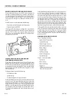
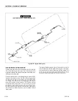
FUEL METERING SYSTEM PURPOSE
The basic function of the air/fuel metering system is to control
the air/fuel delivery to the engine. Fuel is delivered to the
engine by individual fuel injectors mounted in the intake man-
ifold near each intake valve.
The main control sensor is the heated oxygen sensor (H02S)
located in the exhaust system. The H02S tells the Engine Mod-
ule how much oxygen is in the exhaust gas. The Engine Mod-
ule changes the air/fuel ratio to the engine by control-ling the
amount of time that the fuel injector is "ON." The best mixture
to minimize exhaust emissions is 14.7 parts of air to 1 part of
gasoline by weight, which provides the most efficient com-
bustion. Because of the constant measuring and adjusting of
the air/fuel ratio, the fuel injection system is called a "closed
loop" system.
The Engine Module monitors signals from several sensors in
order to determine the fuel needs of the engine. Fuel is deliv-
ered under one of several conditions called "modes." All
modes are controlled by the Engine Module. Refer to "Open
Loop and Closed Loop Operation" for more information.
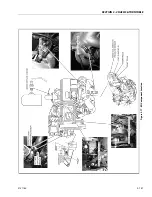
Figure 3-79. Typical Fuel System
HIGH PRESSURE CIRCUIT - OPERATING PRESSURE 65 PSI.
Summary of Contents for 740AJ
Page 2: ......
Page 55: ...SECTION 3 CHASSIS TURNTABLE 3121160 3 3 This page left blank intentionally...
Page 116: ...SECTION 3 CHASSIS TURNTABLE 3 64 3121160 Figure 3 44 Swing Hub Prior to SN 0300074383...
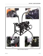
Page 203: ...SECTION 3 CHASSIS TURNTABLE 3121160 3 151 Figure 3 77 EFI Component Location...
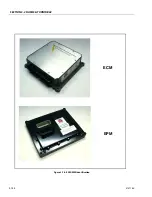
Page 206: ...SECTION 3 CHASSIS TURNTABLE 3 154 3121160 Figure 3 78 ECM EPM Identification ECM EPM...
Page 224: ...SECTION 3 CHASSIS TURNTABLE 3 172 3121160 Figure 3 83 Deutz EMR 2 Troubleshooting Flow Chart...
Page 228: ...SECTION 3 CHASSIS TURNTABLE 3 176 3121160 Figure 3 87 EMR 2 Engine Plug Pin Identification...
Page 229: ...SECTION 3 CHASSIS TURNTABLE 3121160 3 177 Figure 3 88 EMR 2 Vehicle Plug Pin Identification...
Page 230: ...SECTION 3 CHASSIS TURNTABLE 3 178 3121160 Figure 3 89 EMR2 Fault Codes Sheet 1 of 5...
Page 231: ...SECTION 3 CHASSIS TURNTABLE 3121160 3 179 Figure 3 90 EMR2 Fault Codes Sheet 2 of 5...
Page 232: ...SECTION 3 CHASSIS TURNTABLE 3 180 3121160 Figure 3 91 EMR2 Fault Codes Sheet 3 of 5...
Page 233: ...SECTION 3 CHASSIS TURNTABLE 3121160 3 181 Figure 3 92 EMR2 Fault Codes Sheet 4 of 5...
Page 234: ...SECTION 3 CHASSIS TURNTABLE 3 182 3121160 Figure 3 93 EMR2 Fault Codes Sheet 5 of 5...
Page 303: ...SECTION 4 BOOM PLATFORM 3121160 4 31 Figure 4 20 Rotator Assembly HELAC...
Page 460: ...SECTION 5 BASIC HYDRAULIC INFORMATION AND SCHEMATICS 5 116 3121160 NOTES...
Page 467: ...SECTION 6 JLG CONTROL SYSTEM 3121160 6 7 Figure 6 2 ADE Block Diagram...
Page 534: ...SECTION 6 JLG CONTROL SYSTEM 6 74 3121160 NOTES...
Page 580: ...SECTION 7 BASIC ELECTRICAL INFORMATION SCHEMATICS 7 46 3121160 NOTES...
Page 581: ......

