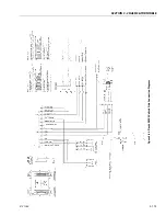
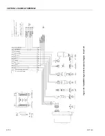
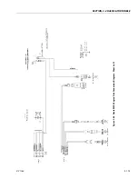


SECTION 3 - CHASSIS & TURNTABLE
3121160
3-183
3.32 GM ENGINE GENERAL MAINTENANCE
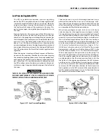
Maintenance of the Drive Belt
The serpentine drive belt utilizes a spring loaded tensioner
which keeps the belt properly adjusted. The drive belt is an
integral part of the cooling and charging systems and should
be inspected frequently.
When inspecting the belts check for:
• Cracks or breaks
• Chunking of the belt
• Splits
• Material hanging from the belt
• Glazing and hardening
• Damaged or improperly aligned pulleys
• Improperly performing tensioner
Check the belt tensioner by pressing down on the midway
point of the longest stretch between pulleys. The belt should
not depress beyond 1/2 in. (13mm). If the depression is more
than allowable adjust the tension.
THE ENGINE MANUFACTURER DOES NOT RECOMMEND THE USE OF "BELT
DRESSING" OR "ANTI SLIPPING AGENTS" ON THE DRIVE BELT.
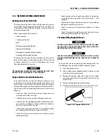
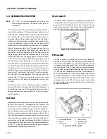
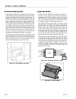
Engine Electrical System Maintenance
The engine electrical system incorporates computers and
microprocessors to control the engine ignition, fuel control,
and emissions. Due to the sensitivity of the computers to good
electrical connections periodic inspection of the electrical wir-
ing is necessary. When inspecting the electrical system use the
following:
• Check and clean the battery terminal connections and
insure the connections are tight
• Check the battery for any cracks or damage to the case
• Check the Positive and Negative battery cables for any cor-
rosion build up, rubbing or chafing, check connection on
the chassis to insure they are tight
• Check the entire engine wire harness for rubbing chafing,
cuts or damaged connections, repair if necessary
• Check all wire harness connectors to insure they are fully
seated and locked
• Check ignition coil and spark plug cables for hardening,
cracking, chafing, separation, split boot covers and
proper fit
• Replace spark plugs at the proper intervals as prescribed in
the engine manufacturer’s manual
• Check to make sure all electrical components are fitted
securely
• Check the ground and platform control stations to insure
all warning indicator lights are functioning
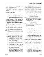
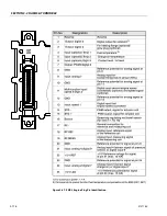
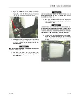
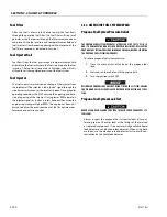
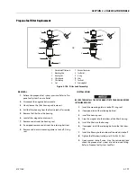
Checking/Filling Engine Oil Level
AN OVERFILLED CRANKCASE (OIL LEVEL OVER THE SPECIFIED FULL MARK)
CAN CAUSE AN OIL LEAK, A FLUCTUATION OR DROP IN THE OIL PRESSURE,
AND ROCKER ARM "CLATTER" IN THE ENGINE.
CARE MUST BE TAKEN WHEN CHECKING THE ENGINE OIL LEVEL. OIL LEVEL
MUST BE MAINTAINED BETWEEN THE "ADD" MARK AND "FULL" MARK ON THE
DIPSTICK.
To ensure that you are not getting a false reading, make sure
the following steps are taken to before check the oil level.
1.
Stop the engine if in use.
2.
Allow sufficient time (approximately 5 minutes) for the
oil to drain back into the oil pan.
3.
Remove the dipstick. Wipe with a clean cloth or paper
towel and reinstall. Push the dipstick all the way into the
dipstick tube.
4.
Remove the dipstick and note the oil level.
5.
Oil level must be between the "FULL" and "ADD" marks.
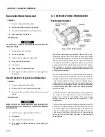
Figure 3-94. Engine Oil Dip Stick
Summary of Contents for 740AJ
Page 2: ......
Page 55: ...SECTION 3 CHASSIS TURNTABLE 3121160 3 3 This page left blank intentionally...
Page 116: ...SECTION 3 CHASSIS TURNTABLE 3 64 3121160 Figure 3 44 Swing Hub Prior to SN 0300074383...
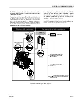
Page 203: ...SECTION 3 CHASSIS TURNTABLE 3121160 3 151 Figure 3 77 EFI Component Location...
Page 206: ...SECTION 3 CHASSIS TURNTABLE 3 154 3121160 Figure 3 78 ECM EPM Identification ECM EPM...
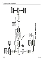
Page 224: ...SECTION 3 CHASSIS TURNTABLE 3 172 3121160 Figure 3 83 Deutz EMR 2 Troubleshooting Flow Chart...
Page 228: ...SECTION 3 CHASSIS TURNTABLE 3 176 3121160 Figure 3 87 EMR 2 Engine Plug Pin Identification...
Page 229: ...SECTION 3 CHASSIS TURNTABLE 3121160 3 177 Figure 3 88 EMR 2 Vehicle Plug Pin Identification...
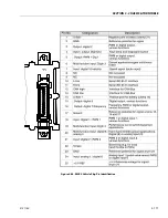
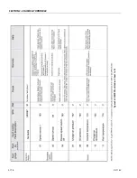
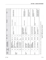
Page 230: ...SECTION 3 CHASSIS TURNTABLE 3 178 3121160 Figure 3 89 EMR2 Fault Codes Sheet 1 of 5...
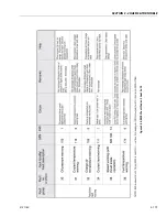
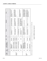
Page 231: ...SECTION 3 CHASSIS TURNTABLE 3121160 3 179 Figure 3 90 EMR2 Fault Codes Sheet 2 of 5...
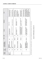
Page 232: ...SECTION 3 CHASSIS TURNTABLE 3 180 3121160 Figure 3 91 EMR2 Fault Codes Sheet 3 of 5...
Page 233: ...SECTION 3 CHASSIS TURNTABLE 3121160 3 181 Figure 3 92 EMR2 Fault Codes Sheet 4 of 5...
Page 234: ...SECTION 3 CHASSIS TURNTABLE 3 182 3121160 Figure 3 93 EMR2 Fault Codes Sheet 5 of 5...
Page 303: ...SECTION 4 BOOM PLATFORM 3121160 4 31 Figure 4 20 Rotator Assembly HELAC...
Page 460: ...SECTION 5 BASIC HYDRAULIC INFORMATION AND SCHEMATICS 5 116 3121160 NOTES...
Page 467: ...SECTION 6 JLG CONTROL SYSTEM 3121160 6 7 Figure 6 2 ADE Block Diagram...
Page 534: ...SECTION 6 JLG CONTROL SYSTEM 6 74 3121160 NOTES...
Page 580: ...SECTION 7 BASIC ELECTRICAL INFORMATION SCHEMATICS 7 46 3121160 NOTES...
Page 581: ......