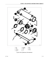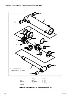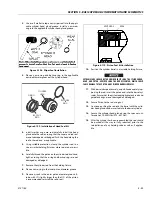
SECTION 5 - BASIC HYDRAULIC INFOR
M
ATION AND SCHE
M
ATICS
3121160
5-41
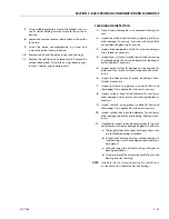
14.
Inspect travel limiting collar or spacer for burrs and
sharp edges. If necessary, dress inside diameter surface
with Scotch Brite or equivalent.
15.
Inspect port block fittings and holding valve. Replace as
necessary.
16.
Inspect the oil ports for blockage or the presence of dirt
or other foreign material. Repair as necessary.
17.
If applicable, inspect piston rings for cracks or other
damage. Replace as necessary.
ASSEMBLY
NOTE:
Prior to cylinder assembly, ensure that the proper cylinder
seal kit is used. See your JLG Parts Manual.
NOTE:
Apply a light film of hydraulic oil to all components prior to
assembly.
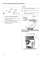
1.
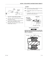
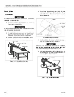
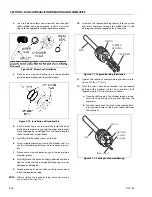
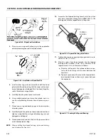
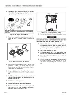
A special tool is used to install a new rod seal into the
applicable cylinder head gland groove.
WHEN INSTALLING NEW SEALS, ENSURE SEALS ARE INSTALLED PROPERLY.
IMPROPER SEAL INSTALLATION COULD RESULT IN CYLINDER LEAKAGE AND
IMPROPER CYLINDER OPERATION.
2.
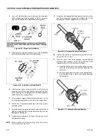
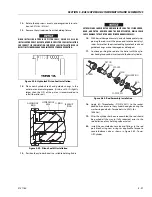
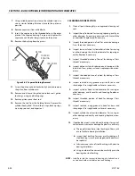
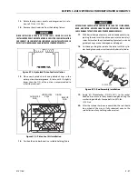
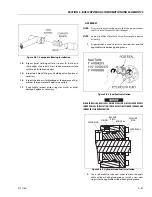
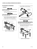
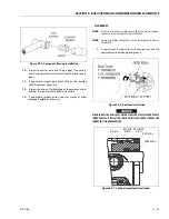
Use a soft mallet to tap a new wiper seal into the appli-
cable cylinder head gland groove. Install a new wear
rings into the applicable cylinder head gland groove.
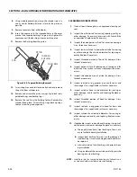
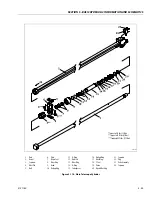
Figure 5-81. Composite Bearing Installation
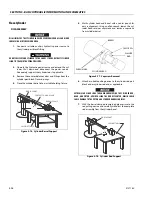
Figure 5-82. Rod Seal Installation
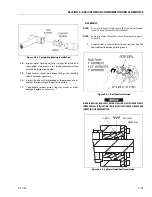
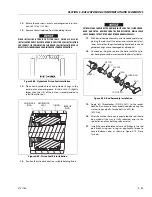
Figure 5-83. Cylinder Head Seal Installation
WASHER
RING
O-RING
BACKUP
RING
ROD SEAL
WIPER SEAL
WEAR RING
Summary of Contents for 740AJ
Page 2: ......
Page 55: ...SECTION 3 CHASSIS TURNTABLE 3121160 3 3 This page left blank intentionally...
Page 116: ...SECTION 3 CHASSIS TURNTABLE 3 64 3121160 Figure 3 44 Swing Hub Prior to SN 0300074383...
Page 203: ...SECTION 3 CHASSIS TURNTABLE 3121160 3 151 Figure 3 77 EFI Component Location...
Page 206: ...SECTION 3 CHASSIS TURNTABLE 3 154 3121160 Figure 3 78 ECM EPM Identification ECM EPM...
Page 224: ...SECTION 3 CHASSIS TURNTABLE 3 172 3121160 Figure 3 83 Deutz EMR 2 Troubleshooting Flow Chart...
Page 228: ...SECTION 3 CHASSIS TURNTABLE 3 176 3121160 Figure 3 87 EMR 2 Engine Plug Pin Identification...
Page 229: ...SECTION 3 CHASSIS TURNTABLE 3121160 3 177 Figure 3 88 EMR 2 Vehicle Plug Pin Identification...
Page 230: ...SECTION 3 CHASSIS TURNTABLE 3 178 3121160 Figure 3 89 EMR2 Fault Codes Sheet 1 of 5...
Page 231: ...SECTION 3 CHASSIS TURNTABLE 3121160 3 179 Figure 3 90 EMR2 Fault Codes Sheet 2 of 5...
Page 232: ...SECTION 3 CHASSIS TURNTABLE 3 180 3121160 Figure 3 91 EMR2 Fault Codes Sheet 3 of 5...
Page 233: ...SECTION 3 CHASSIS TURNTABLE 3121160 3 181 Figure 3 92 EMR2 Fault Codes Sheet 4 of 5...
Page 234: ...SECTION 3 CHASSIS TURNTABLE 3 182 3121160 Figure 3 93 EMR2 Fault Codes Sheet 5 of 5...
Page 303: ...SECTION 4 BOOM PLATFORM 3121160 4 31 Figure 4 20 Rotator Assembly HELAC...
Page 460: ...SECTION 5 BASIC HYDRAULIC INFORMATION AND SCHEMATICS 5 116 3121160 NOTES...
Page 467: ...SECTION 6 JLG CONTROL SYSTEM 3121160 6 7 Figure 6 2 ADE Block Diagram...
Page 534: ...SECTION 6 JLG CONTROL SYSTEM 6 74 3121160 NOTES...
Page 580: ...SECTION 7 BASIC ELECTRICAL INFORMATION SCHEMATICS 7 46 3121160 NOTES...
Page 581: ......

