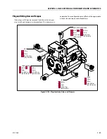
SECTION 5 - BASIC HYDRAULIC INFOR
M
ATION AND SCHE
M
ATICS
3121160
5-77
5.
Platform Level Up
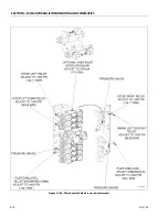
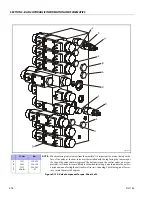
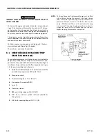
Install a high pressure gauge at port
“M3”, located on the
right side of the block at the bottom. There is pressure
trapped at this test port. To release this pressure, acti-
vate level down to the end of stroke (the pressure in the
up side goes to 0). This will allow you to snap a gauge on
this port. Activate level up to the end of stroke, you
should read
2600 psi (179 bar). This is what the pump
high pressure valve is set at. We want level up to read
2800 psi (193 bar). The level up relief valve is located in
front of the “M3” gauge port. When activating level up,
and reading 2600 psi (179 bar), turn the adjustment
counterclockwise until the pressure drops below 2600
psi (179 bar), turn clockwise (slowly) until the gauge
stops moving. It should stop at
2600 psi (179 bar), turn
clockwise 1/2 turn and lock. This will give you 2800 psi
(193 bar) on level up. This pressure is required to keep
the platform level when the boom is being lowered.
6.
Platform Level Down
Install a high pressure gauge at the “M4” port located on
the left of the valve near the bottom. To get a gauge on
this point, activate level up to the end of stroke (the
pressure in the down side will go to 0, allowing you to
snap a gauge on). Activate level down to the end of
stroke, reading 1800 psi (124 bar). The level down relief
valve is located on the right side of the block above the
“M4” port. Turn clockwise to increase, and counterclock-
wise to decrease.
7.
Articulating Jib Up
Install a high pressure gauge on the gauge port of the
jib block located on the top of the main valve block. The
gauge port has a 12 in. hose plumbed into it for easy
access. Activate jib up, you should read 2500 psi (172
bar). The up relief valve is located on the right side of the
jib block toward the front. Turn clockwise to increase,
and counterclockwise to decrease.
8.
Articulating Jib Down
Install a high pressure gauge on the gauge port of the
jib block located on top of the main valve block. The
gauge port has a 12 in. hose plumbed into it for easy
access. Activate jib down, you should read 1200 psi (83
bar). The down relief valve is located on the right side of
the jib block toward the back. Turn clockwise to
increase, and counterclockwise to decrease.
4 Wheel Steer (If Equipped)
1.
At the platform console using the steer select switch
activate “4 wheel steer”.
2.
Install a pressure gauge in port
"G"
on main control
valve.
3.
With the aid of an assistant, activate steer left and right,
adjust front steer relief valve to
2500 psi
(172 bar). This
pressure only affects the front axle.
4.
At the platform console using the steer select switch
activate “crab” or “coordinated” steer.
5.
At the main control valve block disconnect the wire din
connectors on the front steer valve. When steer is acti-
vated only the rear steer will work.
6.
Install a pressure gauge in port
"G"
on main control
valve.
7.
With the aid of an assistant, activate steer left and right,
adjust rear steer relief valve to
2500 psi
(172 bar) Read-
ing at the valve bank.
2500 psi
(172 bar) will give you
2000 psi
(138 bar) at the cylinders.
8.
Re-connect the front steer din connectors at the valve
bank.
Summary of Contents for 740AJ
Page 2: ......
Page 55: ...SECTION 3 CHASSIS TURNTABLE 3121160 3 3 This page left blank intentionally...
Page 116: ...SECTION 3 CHASSIS TURNTABLE 3 64 3121160 Figure 3 44 Swing Hub Prior to SN 0300074383...
Page 203: ...SECTION 3 CHASSIS TURNTABLE 3121160 3 151 Figure 3 77 EFI Component Location...
Page 206: ...SECTION 3 CHASSIS TURNTABLE 3 154 3121160 Figure 3 78 ECM EPM Identification ECM EPM...
Page 224: ...SECTION 3 CHASSIS TURNTABLE 3 172 3121160 Figure 3 83 Deutz EMR 2 Troubleshooting Flow Chart...
Page 228: ...SECTION 3 CHASSIS TURNTABLE 3 176 3121160 Figure 3 87 EMR 2 Engine Plug Pin Identification...
Page 229: ...SECTION 3 CHASSIS TURNTABLE 3121160 3 177 Figure 3 88 EMR 2 Vehicle Plug Pin Identification...
Page 230: ...SECTION 3 CHASSIS TURNTABLE 3 178 3121160 Figure 3 89 EMR2 Fault Codes Sheet 1 of 5...
Page 231: ...SECTION 3 CHASSIS TURNTABLE 3121160 3 179 Figure 3 90 EMR2 Fault Codes Sheet 2 of 5...
Page 232: ...SECTION 3 CHASSIS TURNTABLE 3 180 3121160 Figure 3 91 EMR2 Fault Codes Sheet 3 of 5...
Page 233: ...SECTION 3 CHASSIS TURNTABLE 3121160 3 181 Figure 3 92 EMR2 Fault Codes Sheet 4 of 5...
Page 234: ...SECTION 3 CHASSIS TURNTABLE 3 182 3121160 Figure 3 93 EMR2 Fault Codes Sheet 5 of 5...
Page 303: ...SECTION 4 BOOM PLATFORM 3121160 4 31 Figure 4 20 Rotator Assembly HELAC...
Page 460: ...SECTION 5 BASIC HYDRAULIC INFORMATION AND SCHEMATICS 5 116 3121160 NOTES...
Page 467: ...SECTION 6 JLG CONTROL SYSTEM 3121160 6 7 Figure 6 2 ADE Block Diagram...
Page 534: ...SECTION 6 JLG CONTROL SYSTEM 6 74 3121160 NOTES...
Page 580: ...SECTION 7 BASIC ELECTRICAL INFORMATION SCHEMATICS 7 46 3121160 NOTES...
Page 581: ......

