


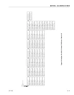


SECTION 6 - JLG CONTROL SYSTE
M
6-2
3121160
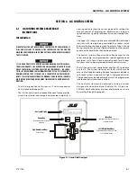
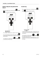
To Connect the JLG Control System Analyzer
1.
Connect one end of the cable, supplied with the ana-
lyzer, to the correct four pin connector on the motor
control unit; there will be only one connector which cor-
rectly fits the cable.
2.
Connect the other end of the cable to the analyzer.
NOTE:
The ends of the cable are identical and can be reversed; the
cable end can only be inserted one way into the matching
connector.
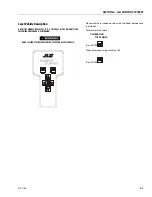
3.
Power up the vehicle by turning the key to the platform
or ground position and pulling the emergency stop but-
tons on; this will power the SMART System and the ana-
lyzer.
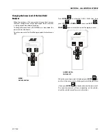
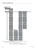
Using the Analyzer
The analyzer will display the current top level menu item, for
example::
MENU:
DIAGNOSTICS
Press LEFT & RIGHT to move between menu items; press
ENTER to select the displayed menu item.
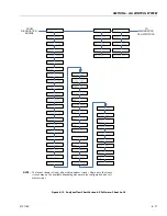
When a top level menu item is selected, a new set of menu
items may be offered; press
LEFT
&
RIGHT
arrows
then
ENTER
again to select the required item.
To cancel a selected menu item, press
ESCAPE
; then a
different menu item can be chosen.
The available menu items will vary depending on the vehicle;
check the vehicle manual for more information.
Summary of Contents for 740AJ
Page 2: ......
Page 55: ...SECTION 3 CHASSIS TURNTABLE 3121160 3 3 This page left blank intentionally...
Page 116: ...SECTION 3 CHASSIS TURNTABLE 3 64 3121160 Figure 3 44 Swing Hub Prior to SN 0300074383...
Page 203: ...SECTION 3 CHASSIS TURNTABLE 3121160 3 151 Figure 3 77 EFI Component Location...
Page 206: ...SECTION 3 CHASSIS TURNTABLE 3 154 3121160 Figure 3 78 ECM EPM Identification ECM EPM...
Page 224: ...SECTION 3 CHASSIS TURNTABLE 3 172 3121160 Figure 3 83 Deutz EMR 2 Troubleshooting Flow Chart...
Page 228: ...SECTION 3 CHASSIS TURNTABLE 3 176 3121160 Figure 3 87 EMR 2 Engine Plug Pin Identification...
Page 229: ...SECTION 3 CHASSIS TURNTABLE 3121160 3 177 Figure 3 88 EMR 2 Vehicle Plug Pin Identification...
Page 230: ...SECTION 3 CHASSIS TURNTABLE 3 178 3121160 Figure 3 89 EMR2 Fault Codes Sheet 1 of 5...
Page 231: ...SECTION 3 CHASSIS TURNTABLE 3121160 3 179 Figure 3 90 EMR2 Fault Codes Sheet 2 of 5...
Page 232: ...SECTION 3 CHASSIS TURNTABLE 3 180 3121160 Figure 3 91 EMR2 Fault Codes Sheet 3 of 5...
Page 233: ...SECTION 3 CHASSIS TURNTABLE 3121160 3 181 Figure 3 92 EMR2 Fault Codes Sheet 4 of 5...
Page 234: ...SECTION 3 CHASSIS TURNTABLE 3 182 3121160 Figure 3 93 EMR2 Fault Codes Sheet 5 of 5...
Page 303: ...SECTION 4 BOOM PLATFORM 3121160 4 31 Figure 4 20 Rotator Assembly HELAC...
Page 460: ...SECTION 5 BASIC HYDRAULIC INFORMATION AND SCHEMATICS 5 116 3121160 NOTES...
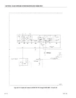
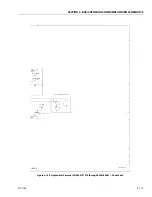
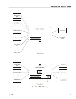
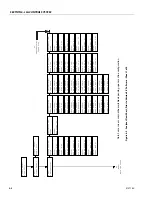
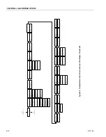
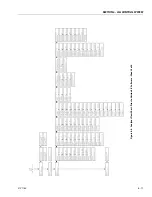
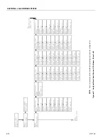
Page 467: ...SECTION 6 JLG CONTROL SYSTEM 3121160 6 7 Figure 6 2 ADE Block Diagram...
Page 534: ...SECTION 6 JLG CONTROL SYSTEM 6 74 3121160 NOTES...
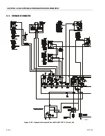
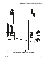
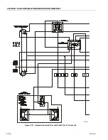
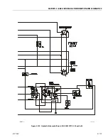
Page 580: ...SECTION 7 BASIC ELECTRICAL INFORMATION SCHEMATICS 7 46 3121160 NOTES...
Page 581: ......