SECTION 3 - CHASSIS & TURNTABLE
3-8
3121160
3.3
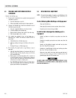
WHEEL DRIVE ASSEMBLY (PRIOR TO SN
0300138447)
Removal
NOTE:
The drive motor can be removed through the axle flange as
part of the wheel drive assembly or they can be removed
separately through the bottom of the frame while leaving
the drive hub bolted to the axle.
1.
Use a jack to lift the frame enough so the tire and wheel
assembly is off the ground. Place blocking strong
enough to support the weight of the machine under the
frame and remove the jack.
NOTE:
The foam-filled tire & wheel assembly weighs approxi-
mately 601 lbs. (273 kg).
2.
Remove hardware securing wheel and remove wheel
assembly. Using suitable lifting device lift the wheel
assembly and place in a suitable area.
3.
Through the access holes in the axle, tag and disconnect
the hydraulic lines running to the drive motor. Cap or
plug all openings to ensure no dirt enters the hydraulic
system.
NOTE:
The drive hub, drive brake, and drive motor assembly
weighs approximately 275 lbs. (125 kg).
4.
Use a supporting device capable of handling the weight
of the drive hub, drive brake, and drive motor and
unbolt the drive hub from the frame. Remove the entire
assembly from the machine.
5.
Remove the nuts and washers that secure the drive
motor to the drive hub and drive brake and remove the
drive motor.
6.
Remove the drive brake from the drive hub. If necessary,
remove the studs from the drive hub.
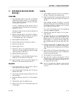
Installation
1.
Apply coat of JLG Threadlocker P/N 0100011 on studs.
Install the studs on the drive hub. Slide the drive brake
and drive motor over the studs.
2.
Install the washers and nuts to secure the assembly
together and torque the nuts.
3.
Place the drive hub flange against the mounting flange
on the axle and fasten it in place with the bolts and
washers. Torque the bolts to 190 ft. lbs. (260 Nm).
4.
Using adequate support, install wheel into wheel
assembly and secure with bolts and washers.
NOTE:
Torque the bolts to 300 ft. lbs. (407 Nm).
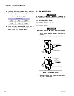
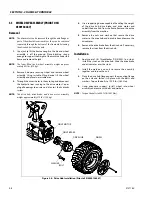
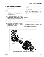
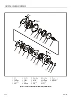
Figure 3-6. Drive Hub Installation (Prior to SN 0300138447)
DRIVE BRAKE
DRIVE HUB
WHEEL
BOLT
WASHER
DRIVE MOTOR
Summary of Contents for 740AJ
Page 2: ......
Page 55: ...SECTION 3 CHASSIS TURNTABLE 3121160 3 3 This page left blank intentionally...
Page 116: ...SECTION 3 CHASSIS TURNTABLE 3 64 3121160 Figure 3 44 Swing Hub Prior to SN 0300074383...
Page 203: ...SECTION 3 CHASSIS TURNTABLE 3121160 3 151 Figure 3 77 EFI Component Location...
Page 206: ...SECTION 3 CHASSIS TURNTABLE 3 154 3121160 Figure 3 78 ECM EPM Identification ECM EPM...
Page 224: ...SECTION 3 CHASSIS TURNTABLE 3 172 3121160 Figure 3 83 Deutz EMR 2 Troubleshooting Flow Chart...
Page 228: ...SECTION 3 CHASSIS TURNTABLE 3 176 3121160 Figure 3 87 EMR 2 Engine Plug Pin Identification...
Page 229: ...SECTION 3 CHASSIS TURNTABLE 3121160 3 177 Figure 3 88 EMR 2 Vehicle Plug Pin Identification...
Page 230: ...SECTION 3 CHASSIS TURNTABLE 3 178 3121160 Figure 3 89 EMR2 Fault Codes Sheet 1 of 5...
Page 231: ...SECTION 3 CHASSIS TURNTABLE 3121160 3 179 Figure 3 90 EMR2 Fault Codes Sheet 2 of 5...
Page 232: ...SECTION 3 CHASSIS TURNTABLE 3 180 3121160 Figure 3 91 EMR2 Fault Codes Sheet 3 of 5...
Page 233: ...SECTION 3 CHASSIS TURNTABLE 3121160 3 181 Figure 3 92 EMR2 Fault Codes Sheet 4 of 5...
Page 234: ...SECTION 3 CHASSIS TURNTABLE 3 182 3121160 Figure 3 93 EMR2 Fault Codes Sheet 5 of 5...
Page 303: ...SECTION 4 BOOM PLATFORM 3121160 4 31 Figure 4 20 Rotator Assembly HELAC...
Page 460: ...SECTION 5 BASIC HYDRAULIC INFORMATION AND SCHEMATICS 5 116 3121160 NOTES...
Page 467: ...SECTION 6 JLG CONTROL SYSTEM 3121160 6 7 Figure 6 2 ADE Block Diagram...
Page 534: ...SECTION 6 JLG CONTROL SYSTEM 6 74 3121160 NOTES...
Page 580: ...SECTION 7 BASIC ELECTRICAL INFORMATION SCHEMATICS 7 46 3121160 NOTES...
Page 581: ......

