SECTION 6 - JLG CONTROL SYSTE
M
3121160
6-37
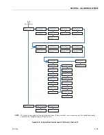
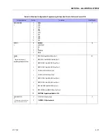
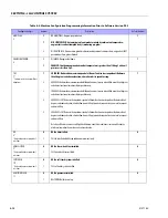
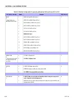
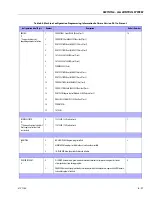
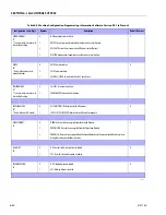
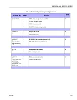
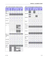
ENGINE:
3*
* Engine selections vary
depending on model selection.
1
2
3
4
5
6
7
8
9
10
11
12
13
14
15
FORD EFI GAS: Ford LRG425 EFI Gas (Tier 1)
FORD EFI D/F: Ford LRG425 EFI dual fuel (Tier 1)
DEUTZ F4 TIER1: Deutz F4M1011F Diesel (Tier 1)
DEUTZ F3 TIER1: Deutz F3M1011F Diesel (Tier 1)
CAT. 3024C: CAT 3024C Diesel (Tier 2)
CAT. 3044C: CAT 3044C Diesel (Tier 2)
PERKINS 404C (Tier 2)
DEUTZ F4 TIER2: Deutz F4M2011 Diesel (Tier 2)
DEUTZ F3 TIER2: Deutz F3M2011 Diesel (Tier 2)
FORD GAS TIER2: Ford LRG425 EFI Gas (Tier 2)
FORD D/F TIER2: Ford LRG425 EFI Dual Fuel (Tier 2)
DEUTZ ECM: Engine Control Module - ECM (Tier 2 and Tier 3)
DUAL FUEL ECM: GM/PSI 3.0L Dual Fuel (Tier 2)
PERKINS ECM
CAT ECM
14
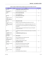
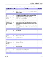
FLYWHEEL TEETH:
4*
* This menu item is only visible if
Deutz engine selections 3 or 4
are selected.
0
1
133 TEETH: 133 flywheel teeth.
110 TEETH: 110 flywheel teeth.
1
GLOW PLUG:
5
0
1
2
NO GLOW PLUGS: No glow plugs installed.
AIR INTAKE: Glow plugs installed in the air intake on the manifold.
IN-CYLINDER: Glow plugs installed in each cylinder.
2
STARTER LOCKOUT:
6
0
1
DISABLED: Automatic pre-glow time determined by ambient air temperature; engine start can be
attempted at any time during pre-glow.
ENABLED: Automatic pre-glow time determined by ambient air temperature; engine start is NOT permit-
ted until pre-glow is finished.
0
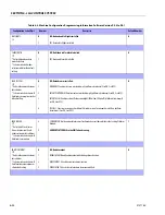
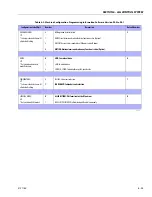
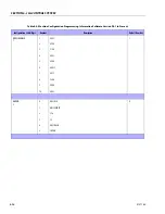
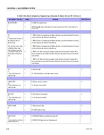
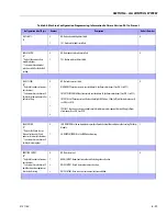
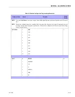
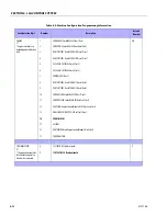
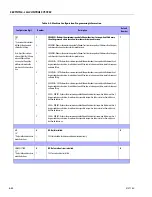
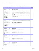
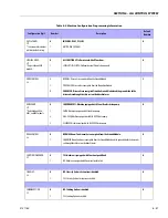
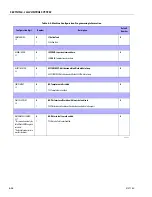
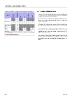
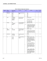
Table 6-4. Machine Configuration Programming Information Software Version P6.1 to Present
Configuration Label/Digit
Number
Description
Default Number
Summary of Contents for 740AJ
Page 2: ......
Page 55: ...SECTION 3 CHASSIS TURNTABLE 3121160 3 3 This page left blank intentionally...
Page 116: ...SECTION 3 CHASSIS TURNTABLE 3 64 3121160 Figure 3 44 Swing Hub Prior to SN 0300074383...
Page 203: ...SECTION 3 CHASSIS TURNTABLE 3121160 3 151 Figure 3 77 EFI Component Location...
Page 206: ...SECTION 3 CHASSIS TURNTABLE 3 154 3121160 Figure 3 78 ECM EPM Identification ECM EPM...
Page 224: ...SECTION 3 CHASSIS TURNTABLE 3 172 3121160 Figure 3 83 Deutz EMR 2 Troubleshooting Flow Chart...
Page 228: ...SECTION 3 CHASSIS TURNTABLE 3 176 3121160 Figure 3 87 EMR 2 Engine Plug Pin Identification...
Page 229: ...SECTION 3 CHASSIS TURNTABLE 3121160 3 177 Figure 3 88 EMR 2 Vehicle Plug Pin Identification...
Page 230: ...SECTION 3 CHASSIS TURNTABLE 3 178 3121160 Figure 3 89 EMR2 Fault Codes Sheet 1 of 5...
Page 231: ...SECTION 3 CHASSIS TURNTABLE 3121160 3 179 Figure 3 90 EMR2 Fault Codes Sheet 2 of 5...
Page 232: ...SECTION 3 CHASSIS TURNTABLE 3 180 3121160 Figure 3 91 EMR2 Fault Codes Sheet 3 of 5...
Page 233: ...SECTION 3 CHASSIS TURNTABLE 3121160 3 181 Figure 3 92 EMR2 Fault Codes Sheet 4 of 5...
Page 234: ...SECTION 3 CHASSIS TURNTABLE 3 182 3121160 Figure 3 93 EMR2 Fault Codes Sheet 5 of 5...
Page 303: ...SECTION 4 BOOM PLATFORM 3121160 4 31 Figure 4 20 Rotator Assembly HELAC...
Page 460: ...SECTION 5 BASIC HYDRAULIC INFORMATION AND SCHEMATICS 5 116 3121160 NOTES...
Page 467: ...SECTION 6 JLG CONTROL SYSTEM 3121160 6 7 Figure 6 2 ADE Block Diagram...
Page 534: ...SECTION 6 JLG CONTROL SYSTEM 6 74 3121160 NOTES...
Page 580: ...SECTION 7 BASIC ELECTRICAL INFORMATION SCHEMATICS 7 46 3121160 NOTES...
Page 581: ......

