SECTION 3 - CHASSIS & TURNTABLE
3121160
3-171
The EMR2 is equipped with safety devices and measures in the
hardware and software in order to ensure emergency running
(Limp home) functions.
In order to switch the engine off, the EMR2 is switched in a de-
energized fashion over the ignition switch. A strong spring in
the actuator presses the control rod in the de-energized con-
dition into the zero position. As a redundancy measure, an
additional solenoid serves for switching off and this, indepen-
dently of the actuator, also moves the control rod in the de-
energized condition into the zero position.
After the programming, that is carried out over the ISO9141
interface, the EMR2 possesses a motor-specific data set and
this is then fixedly assigned to the engine. Included in this are
the various application cases as well as the customer’s wishes
regarding a particular scope of function.
Each EMR2 module is matched by serial number to the engine.
Modules cannot be swapped between engines.
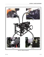
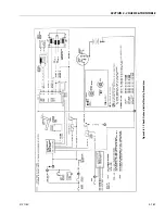
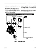
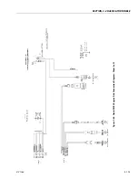
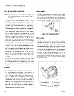
Figure 3-82. EMR 2 Engine Side Equipment
GLOW PLUG
POWER SUPPLY
COOLANT TEMPERATURE
SENSOR
CONTROL ROD POSITION
SENSOR/ACTUATOR
CAMSHAFT SPEED
SENSOR
OIL PRESSURE
SENSOR
JLG SYSTEM USES JLG ANALYZER TO
REPORT FAULTS
DIAGNOSIS INTERFACE/CAN-BUS; JLG SYSTEM
USES THIS TO CONTROL THE ENGINE & FAULT
REPORTING.
JLG SYSTEM HANDLES ENGINE START/
STOP; EMR2 TAKES CONTROL OF THE
ENGINE AT 700RPM
Summary of Contents for 740AJ
Page 2: ......
Page 55: ...SECTION 3 CHASSIS TURNTABLE 3121160 3 3 This page left blank intentionally...
Page 116: ...SECTION 3 CHASSIS TURNTABLE 3 64 3121160 Figure 3 44 Swing Hub Prior to SN 0300074383...
Page 203: ...SECTION 3 CHASSIS TURNTABLE 3121160 3 151 Figure 3 77 EFI Component Location...
Page 206: ...SECTION 3 CHASSIS TURNTABLE 3 154 3121160 Figure 3 78 ECM EPM Identification ECM EPM...
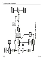
Page 224: ...SECTION 3 CHASSIS TURNTABLE 3 172 3121160 Figure 3 83 Deutz EMR 2 Troubleshooting Flow Chart...
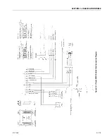
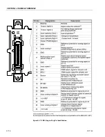
Page 228: ...SECTION 3 CHASSIS TURNTABLE 3 176 3121160 Figure 3 87 EMR 2 Engine Plug Pin Identification...
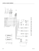
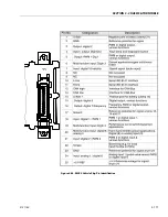
Page 229: ...SECTION 3 CHASSIS TURNTABLE 3121160 3 177 Figure 3 88 EMR 2 Vehicle Plug Pin Identification...
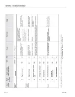
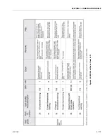
Page 230: ...SECTION 3 CHASSIS TURNTABLE 3 178 3121160 Figure 3 89 EMR2 Fault Codes Sheet 1 of 5...
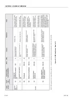
Page 231: ...SECTION 3 CHASSIS TURNTABLE 3121160 3 179 Figure 3 90 EMR2 Fault Codes Sheet 2 of 5...
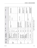
Page 232: ...SECTION 3 CHASSIS TURNTABLE 3 180 3121160 Figure 3 91 EMR2 Fault Codes Sheet 3 of 5...
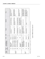
Page 233: ...SECTION 3 CHASSIS TURNTABLE 3121160 3 181 Figure 3 92 EMR2 Fault Codes Sheet 4 of 5...
Page 234: ...SECTION 3 CHASSIS TURNTABLE 3 182 3121160 Figure 3 93 EMR2 Fault Codes Sheet 5 of 5...
Page 303: ...SECTION 4 BOOM PLATFORM 3121160 4 31 Figure 4 20 Rotator Assembly HELAC...
Page 460: ...SECTION 5 BASIC HYDRAULIC INFORMATION AND SCHEMATICS 5 116 3121160 NOTES...
Page 467: ...SECTION 6 JLG CONTROL SYSTEM 3121160 6 7 Figure 6 2 ADE Block Diagram...
Page 534: ...SECTION 6 JLG CONTROL SYSTEM 6 74 3121160 NOTES...
Page 580: ...SECTION 7 BASIC ELECTRICAL INFORMATION SCHEMATICS 7 46 3121160 NOTES...
Page 581: ......

