


SECTION 6 - JLG CONTROL SYSTE
M
6-50
3121160
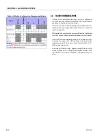
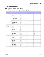
6.2
CANBUS COMMUNICATIONS
CANbus: CAN (Control Area Network) is a two wire differential
serial link between the Platform Module and Ground Module
providing bi-directional communications.
Two-wire: One wire (red) is driven high (5v) and the other low
(black) (0v) to send a signal; both wires ”float” (2.5v) when no
signal is being sent.
Differential: Any electrical line noise can affect the high or the
low wires but never both, so communications is not corrupted.
Serial Link: Messages are being sent bit by bit along the wires;
the high bus speed allow all modules to be constantly
updated around 20 times per second. Typical traffic is 300 -
500 messages per second.
A complete CANbus circuit is approximately 60 ohms, which
can be verified at the ”T” fitting inside the ground station. Each
individual circuit from the modules is approximately 120
ohms.
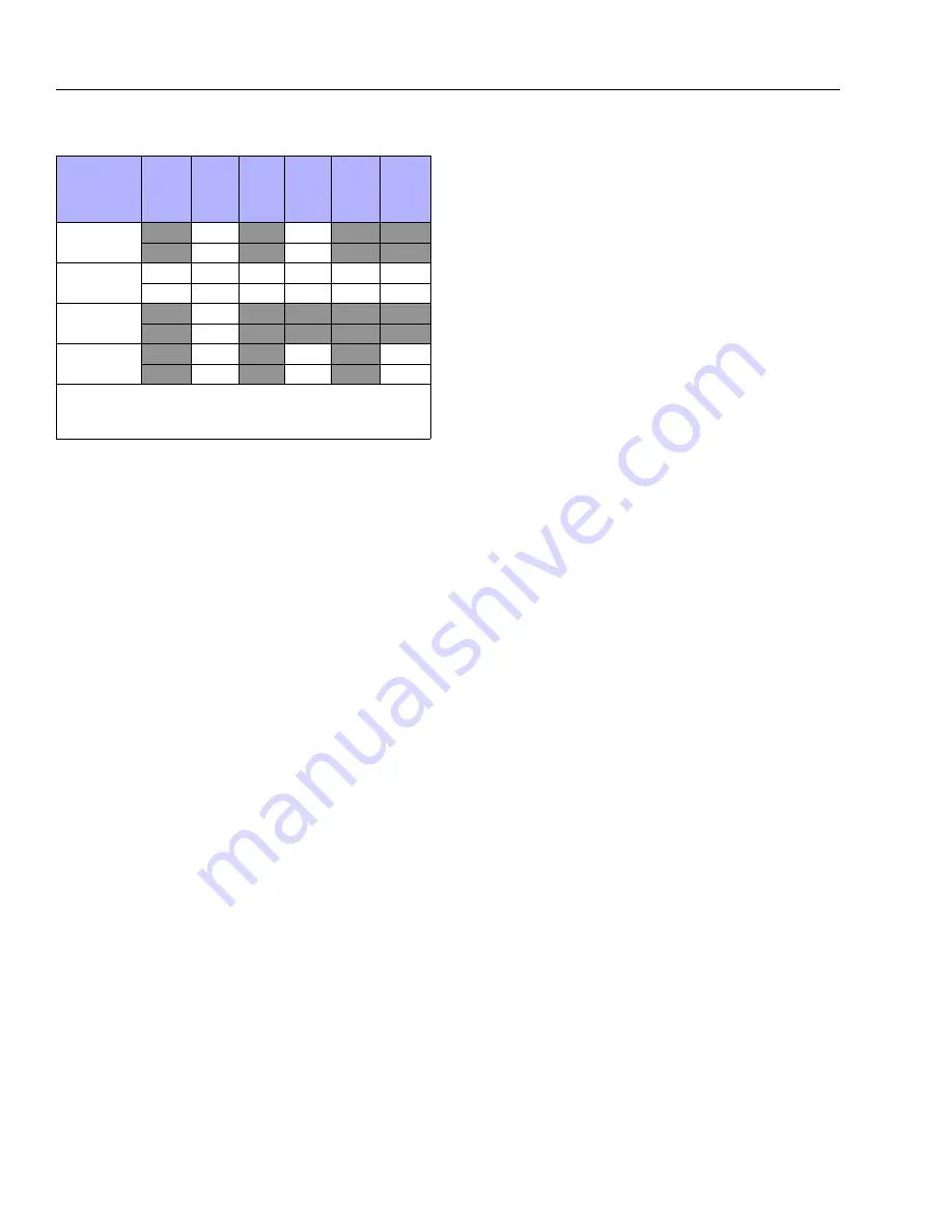
Temp Cutout
X
0
X
0
X
X
X
1
X
1
X
X
Plat Lvl Ovr Cut
0
0
0
0
0
0
1
1
1
1
1
1
Water in Fuel Sen-
sor
X
0
X
X
X
X
X
1
X
X
X
X
Dual
Capacity
0
0
0
0
0
0
1
1
1
1
1
1
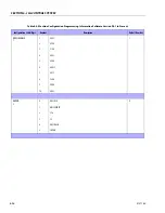
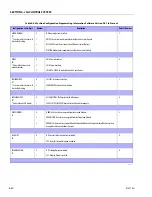
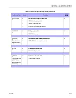
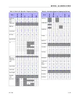
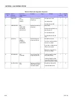
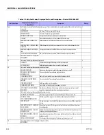
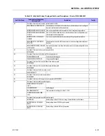
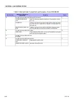
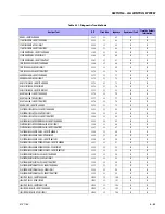
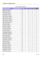
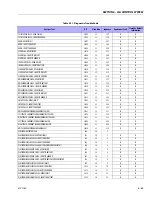
BOLD BLUE
text indicates the default setting. Plain text indicates another available
selection.
RED
ITALIC
text indicates the default when option is factory installed. SHADED
CELLS indicate hidden menu or selection.
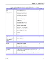
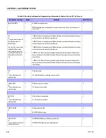
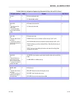
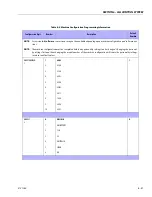
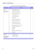
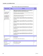
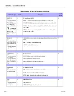
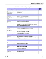
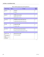
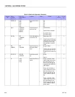
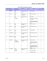
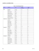
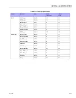
Table 6-6. Machine Configuration Programming Settings
740 AJ
ANSI USA
ANSI Expor
t
CSA
CE
Au
st
ra
lia
Japa
n
Summary of Contents for 740AJ
Page 2: ......
Page 55: ...SECTION 3 CHASSIS TURNTABLE 3121160 3 3 This page left blank intentionally...
Page 116: ...SECTION 3 CHASSIS TURNTABLE 3 64 3121160 Figure 3 44 Swing Hub Prior to SN 0300074383...
Page 203: ...SECTION 3 CHASSIS TURNTABLE 3121160 3 151 Figure 3 77 EFI Component Location...
Page 206: ...SECTION 3 CHASSIS TURNTABLE 3 154 3121160 Figure 3 78 ECM EPM Identification ECM EPM...
Page 224: ...SECTION 3 CHASSIS TURNTABLE 3 172 3121160 Figure 3 83 Deutz EMR 2 Troubleshooting Flow Chart...
Page 228: ...SECTION 3 CHASSIS TURNTABLE 3 176 3121160 Figure 3 87 EMR 2 Engine Plug Pin Identification...
Page 229: ...SECTION 3 CHASSIS TURNTABLE 3121160 3 177 Figure 3 88 EMR 2 Vehicle Plug Pin Identification...
Page 230: ...SECTION 3 CHASSIS TURNTABLE 3 178 3121160 Figure 3 89 EMR2 Fault Codes Sheet 1 of 5...
Page 231: ...SECTION 3 CHASSIS TURNTABLE 3121160 3 179 Figure 3 90 EMR2 Fault Codes Sheet 2 of 5...
Page 232: ...SECTION 3 CHASSIS TURNTABLE 3 180 3121160 Figure 3 91 EMR2 Fault Codes Sheet 3 of 5...
Page 233: ...SECTION 3 CHASSIS TURNTABLE 3121160 3 181 Figure 3 92 EMR2 Fault Codes Sheet 4 of 5...
Page 234: ...SECTION 3 CHASSIS TURNTABLE 3 182 3121160 Figure 3 93 EMR2 Fault Codes Sheet 5 of 5...
Page 303: ...SECTION 4 BOOM PLATFORM 3121160 4 31 Figure 4 20 Rotator Assembly HELAC...
Page 460: ...SECTION 5 BASIC HYDRAULIC INFORMATION AND SCHEMATICS 5 116 3121160 NOTES...
Page 467: ...SECTION 6 JLG CONTROL SYSTEM 3121160 6 7 Figure 6 2 ADE Block Diagram...
Page 534: ...SECTION 6 JLG CONTROL SYSTEM 6 74 3121160 NOTES...
Page 580: ...SECTION 7 BASIC ELECTRICAL INFORMATION SCHEMATICS 7 46 3121160 NOTES...
Page 581: ......