SECTION 1 - SPECIFICATIONS
1-4
3121160
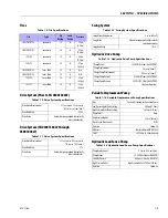
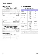
Auxiliary Power Pump
Hydraulic Filter - In-line
1.3
TORQUE REQUIREMENTS
Table 1-16. Auxiliary Power Pump Specifications
(SN 0300069000 through 0300109066)
Pump Output
2.1 GPM (9.5 lpm) @ 1400 psi. (69 bar)
Pump Displacement
0.305 cu. in. (5 cm
3
)
Valving
Non-Adj. Unloader Preset to 230 psi
Adjustable Relief Set at 1800 psi.
Motor
12 V.D.C. 2T Extended EMC Protected Intermittent
Duty
Rotation
Counterclockwise
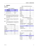
Table 1-17. Auxiliary Power Pump Specifications
(SN 0300109067 through 0300140000)
Pump Output
1.6 GPM (6.057 lpm) @ 1400 psi. (69 bar)
Pump Displacement
0.453 cu. in. (7.4 cm
3
)
Valving
Non-Adj. Unloader Preset to 230 psi
Adjustable Relief Set at 1800 psi.
Motor
12/24 V.D.C. 2T Extended EMC Protected Inter-
mittent Duty
Rotation
Counterclockwise
Table 1-18. Auxiliary Power Pump Specifications
(SN 0300140001 through 0300185827)
Pump Output
1.43GPM (5.4 lpm) @ 1800psi. (124 bar)
Pump Displacement
0.273 cu. in. (4.48 cm
3
)
Motor
24V.D.C. 5.0 Extended Duty
Rotation
Counterclockwise
Table 1-19. Hydraulic FIlter Specifications
Return Filter
10 Microns Absolute
Charge Filter
10 Microns Absolute
Hydraulic Strainers (In Tank)
30 Microns
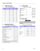
Table 1-20. Torque Requirements
Description
Torque Value (Dry)
Interval Hours
Wheel Bolts
300 ft. lbs.
(407 Nm)
150
Support to Rotator Bolts
85 ft. lbs.
(116 Nm)
150
Rotator Center Bolt
480 ft. lbs.
(651 Nm)
150
Swing Bearing Bolts
190 ft. lbs.
(260 Nm)
50/600*
Starter or Aux Pump
Solenoid
Contacts
Coil
95 in. lbs. (10.5 Nm)
40 in. lbs. (4.5 Nm)
As Required
Oxygen Sensor (Ford Engine)
29.5-40 ft. lbs.
(40-54 Nm)
At Installation
Megajector Mounting Bolts
(Ford Engine)
859 in. lbs.
(97 Nm)
As Required
Lockoff Solenoid (Ford Engine)
8-12 ft. lbs.
(11-16 Nm)
At Installation
*Check swing bearing bolts for security after first 50 hours of operation and every 600
hours thereafter. (See Swing Bearing in Section 3.)
NOTE:
When maintenance becomes necessary or a fastener has loosened, refer to
the Torque Chart to determine proper torque value.
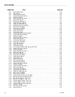
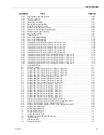
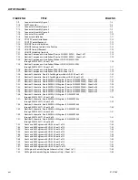
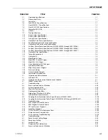
Summary of Contents for 740AJ
Page 2: ......
Page 55: ...SECTION 3 CHASSIS TURNTABLE 3121160 3 3 This page left blank intentionally...
Page 116: ...SECTION 3 CHASSIS TURNTABLE 3 64 3121160 Figure 3 44 Swing Hub Prior to SN 0300074383...
Page 203: ...SECTION 3 CHASSIS TURNTABLE 3121160 3 151 Figure 3 77 EFI Component Location...
Page 206: ...SECTION 3 CHASSIS TURNTABLE 3 154 3121160 Figure 3 78 ECM EPM Identification ECM EPM...
Page 224: ...SECTION 3 CHASSIS TURNTABLE 3 172 3121160 Figure 3 83 Deutz EMR 2 Troubleshooting Flow Chart...
Page 228: ...SECTION 3 CHASSIS TURNTABLE 3 176 3121160 Figure 3 87 EMR 2 Engine Plug Pin Identification...
Page 229: ...SECTION 3 CHASSIS TURNTABLE 3121160 3 177 Figure 3 88 EMR 2 Vehicle Plug Pin Identification...
Page 230: ...SECTION 3 CHASSIS TURNTABLE 3 178 3121160 Figure 3 89 EMR2 Fault Codes Sheet 1 of 5...
Page 231: ...SECTION 3 CHASSIS TURNTABLE 3121160 3 179 Figure 3 90 EMR2 Fault Codes Sheet 2 of 5...
Page 232: ...SECTION 3 CHASSIS TURNTABLE 3 180 3121160 Figure 3 91 EMR2 Fault Codes Sheet 3 of 5...
Page 233: ...SECTION 3 CHASSIS TURNTABLE 3121160 3 181 Figure 3 92 EMR2 Fault Codes Sheet 4 of 5...
Page 234: ...SECTION 3 CHASSIS TURNTABLE 3 182 3121160 Figure 3 93 EMR2 Fault Codes Sheet 5 of 5...
Page 303: ...SECTION 4 BOOM PLATFORM 3121160 4 31 Figure 4 20 Rotator Assembly HELAC...
Page 460: ...SECTION 5 BASIC HYDRAULIC INFORMATION AND SCHEMATICS 5 116 3121160 NOTES...
Page 467: ...SECTION 6 JLG CONTROL SYSTEM 3121160 6 7 Figure 6 2 ADE Block Diagram...
Page 534: ...SECTION 6 JLG CONTROL SYSTEM 6 74 3121160 NOTES...
Page 580: ...SECTION 7 BASIC ELECTRICAL INFORMATION SCHEMATICS 7 46 3121160 NOTES...
Page 581: ......

