SECTION 5 - BASIC HYDRAULIC INFOR
M
ATION AND SCHE
M
ATICS
5-94
3121160
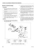
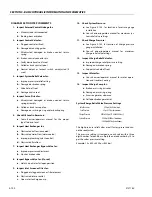
Manual Servo Control Basic Assembly
DISASSEMBLY
1.
Remove wiper seal with screw driver. Remove set screw
retaining input shaft and remove input shaft from con-
trol housing.
2.
Remove set screw from plug retaining valve spool and
remove plug.
3.
Remove o-ring from pin retaining feedback link and
valve spool. Remove pin, feedback link, valve spool, and
bell crank from control housing.
4.
Compress spring and remove o-ring, spring retainer,
spring, and second spring retainer from valve spool.
5.
Remove o-rings from plug and input shaft. Clean all
parts and lubricate in prep for reassembly.
ASSEMBLY
1.
Install spring retainer, spring, and second spring retainer
onto spool. Compress spring with retainer and retain
with o-ring onto valve spool.
2.
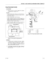
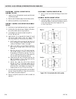
Install valve spool into control housing making sure that
metering notches on valve spool can be seen in the
metering ports. Notches shown in Figure 5-141.
3.
Position bell crank in housing. Slide feedback link into
position between clevis on valve spool, aligning holes,
and install dowel pin retaining with o-ring.
4.
Install new o-ring onto input shaft. Hold bell crank in
position with feedback link slot and align splined hole of
bell crank with input shaft cavity. Install input shaft into
control housing and bell crank.
5.
JLG Threadlocker P/N 0100011 or equivalent to set
screw and install retaining input shaft. Adjust set screw
until it bottoms out on input shaft and back out one-
quarter turn.
6.
Install wiper seal on input shaft as shown in Figure 5-
141. Install new o-ring onto plug. retaining valve spool,
and install plug. Adjust plug until there is no play in the
valve spool with input shaft held stationary. Lock in
place with set screw. Torque set screw 17 to 25 in. lbs.
(2 to 3 Nm).
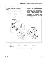
1.
Control Housing
2.
Plug
3.
0-ring
4.
Retaining Ring
5.
Spring Retainer
6.
Spool Centering Spring
7.
Valve Spool
8.
Set Screw
9.
Feedback Link
10. Dowel Pin
11. Retaining Ring
12. Bell Crank
13. Set Screw
14. Input Shaft
15. 0-ri ng
16. Wiper Seal
17. Head Pin
Figure 5-141. Manual Servo Control Basic Assembly
Metering Notches
Wide Band Neutral Spool
Identification Mark
Metering Notches
Wiper Seal
2
3
4
5
6
5
7
1
8
12
10
9
11
17
13
14
15
16
Head pin removal not required
From bell crank.
Summary of Contents for 740AJ
Page 2: ......
Page 55: ...SECTION 3 CHASSIS TURNTABLE 3121160 3 3 This page left blank intentionally...
Page 116: ...SECTION 3 CHASSIS TURNTABLE 3 64 3121160 Figure 3 44 Swing Hub Prior to SN 0300074383...
Page 203: ...SECTION 3 CHASSIS TURNTABLE 3121160 3 151 Figure 3 77 EFI Component Location...
Page 206: ...SECTION 3 CHASSIS TURNTABLE 3 154 3121160 Figure 3 78 ECM EPM Identification ECM EPM...
Page 224: ...SECTION 3 CHASSIS TURNTABLE 3 172 3121160 Figure 3 83 Deutz EMR 2 Troubleshooting Flow Chart...
Page 228: ...SECTION 3 CHASSIS TURNTABLE 3 176 3121160 Figure 3 87 EMR 2 Engine Plug Pin Identification...
Page 229: ...SECTION 3 CHASSIS TURNTABLE 3121160 3 177 Figure 3 88 EMR 2 Vehicle Plug Pin Identification...
Page 230: ...SECTION 3 CHASSIS TURNTABLE 3 178 3121160 Figure 3 89 EMR2 Fault Codes Sheet 1 of 5...
Page 231: ...SECTION 3 CHASSIS TURNTABLE 3121160 3 179 Figure 3 90 EMR2 Fault Codes Sheet 2 of 5...
Page 232: ...SECTION 3 CHASSIS TURNTABLE 3 180 3121160 Figure 3 91 EMR2 Fault Codes Sheet 3 of 5...
Page 233: ...SECTION 3 CHASSIS TURNTABLE 3121160 3 181 Figure 3 92 EMR2 Fault Codes Sheet 4 of 5...
Page 234: ...SECTION 3 CHASSIS TURNTABLE 3 182 3121160 Figure 3 93 EMR2 Fault Codes Sheet 5 of 5...
Page 303: ...SECTION 4 BOOM PLATFORM 3121160 4 31 Figure 4 20 Rotator Assembly HELAC...
Page 460: ...SECTION 5 BASIC HYDRAULIC INFORMATION AND SCHEMATICS 5 116 3121160 NOTES...
Page 467: ...SECTION 6 JLG CONTROL SYSTEM 3121160 6 7 Figure 6 2 ADE Block Diagram...
Page 534: ...SECTION 6 JLG CONTROL SYSTEM 6 74 3121160 NOTES...
Page 580: ...SECTION 7 BASIC ELECTRICAL INFORMATION SCHEMATICS 7 46 3121160 NOTES...
Page 581: ......

