SECTION 6 - JLG CONTROL SYSTE
M
6-60
3121160
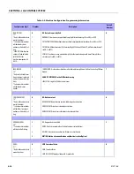
5/5
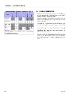
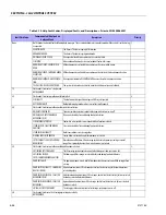
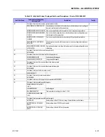
Flash code 5/5 indicates problems with vehicle engine RPM or the encoder.
8
SPEED SENSOR READING INVALID
SPEED
Speed sensor is indicating an impossible number of pulses. This is probably due to a faulty
speed sensor.
SPEED INPUT LOST
This indicates that the control system has determined that the diesel engine speed input to
the system has been lost. This is probably due to wiring problems at the ground module or a
faulty speed sensor.
ENGINE SPEED DOES NOT MATCH COM-
MAND
This indicates that the control system has determine that the diesel engine governor has
stuck. This is probably due to electrical or mechanical problems with the governor.
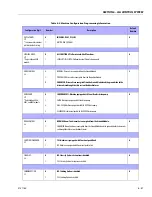
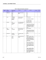
6/6
Flash code 6/6 indicates problems with the CAN bus.
10
CAN BUS FAILURE:
The ground module or platform module is not receiving. This is probably due to wiring prob-
lems between the platform and ground modules.
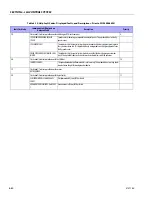
7/7
Flash code 7/7 indicates problems with a motor.
NOT REQUIRED
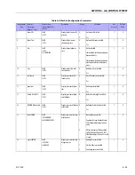
9/9
Flash code 9/9 indicates problems with the controller.
11
PLATFORM MODULE FAILURE: hwfs
CODE 1
Platform module V(Low) FET has failed
GROUND MODULE FAILURE: hwfs CODE
1
Ground module V(Low) FET has failed
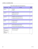
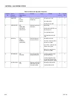
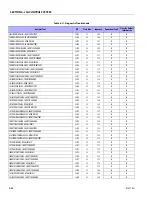
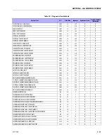
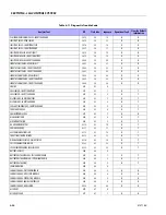
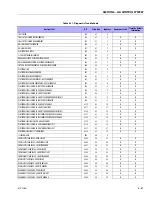
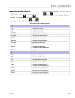
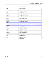
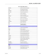
Table 6-10. Help Fault Codes, Displayed Faults, and Descriptions - Prior to SN 0300066931
Fault Flash Code
Communicated (Displayed on
Analyzer) Fault
Description
Priority
Summary of Contents for 740AJ
Page 2: ......
Page 55: ...SECTION 3 CHASSIS TURNTABLE 3121160 3 3 This page left blank intentionally...
Page 116: ...SECTION 3 CHASSIS TURNTABLE 3 64 3121160 Figure 3 44 Swing Hub Prior to SN 0300074383...
Page 203: ...SECTION 3 CHASSIS TURNTABLE 3121160 3 151 Figure 3 77 EFI Component Location...
Page 206: ...SECTION 3 CHASSIS TURNTABLE 3 154 3121160 Figure 3 78 ECM EPM Identification ECM EPM...
Page 224: ...SECTION 3 CHASSIS TURNTABLE 3 172 3121160 Figure 3 83 Deutz EMR 2 Troubleshooting Flow Chart...
Page 228: ...SECTION 3 CHASSIS TURNTABLE 3 176 3121160 Figure 3 87 EMR 2 Engine Plug Pin Identification...
Page 229: ...SECTION 3 CHASSIS TURNTABLE 3121160 3 177 Figure 3 88 EMR 2 Vehicle Plug Pin Identification...
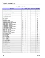
Page 230: ...SECTION 3 CHASSIS TURNTABLE 3 178 3121160 Figure 3 89 EMR2 Fault Codes Sheet 1 of 5...
Page 231: ...SECTION 3 CHASSIS TURNTABLE 3121160 3 179 Figure 3 90 EMR2 Fault Codes Sheet 2 of 5...
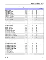
Page 232: ...SECTION 3 CHASSIS TURNTABLE 3 180 3121160 Figure 3 91 EMR2 Fault Codes Sheet 3 of 5...
Page 233: ...SECTION 3 CHASSIS TURNTABLE 3121160 3 181 Figure 3 92 EMR2 Fault Codes Sheet 4 of 5...
Page 234: ...SECTION 3 CHASSIS TURNTABLE 3 182 3121160 Figure 3 93 EMR2 Fault Codes Sheet 5 of 5...
Page 303: ...SECTION 4 BOOM PLATFORM 3121160 4 31 Figure 4 20 Rotator Assembly HELAC...
Page 460: ...SECTION 5 BASIC HYDRAULIC INFORMATION AND SCHEMATICS 5 116 3121160 NOTES...
Page 467: ...SECTION 6 JLG CONTROL SYSTEM 3121160 6 7 Figure 6 2 ADE Block Diagram...
Page 534: ...SECTION 6 JLG CONTROL SYSTEM 6 74 3121160 NOTES...
Page 580: ...SECTION 7 BASIC ELECTRICAL INFORMATION SCHEMATICS 7 46 3121160 NOTES...
Page 581: ......

