SECTION 5 - BASIC HYDRAULIC INFOR
M
ATION AND SCHE
M
ATICS
3121160
5-69
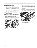
Slave Cylinder Removal
1.
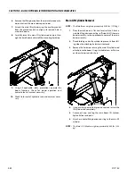
Place the machine on a flat surface and lower the main
boom and tower boom to the lowest position.
2.
Using auxiliary power, retract the slave cylinder rod
completely.
3.
Raise the jib to gain access to the Slave Cylinder piston
end Pin.
NOTE:
The Slave Cylinder weighs approximately 77.15 lbs. (35 kg).
4.
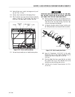
Using a suitable lifting device, properly secure the plat-
form to prevent the platform from tilting backward or
forward during removal of the slave cylinder.
5.
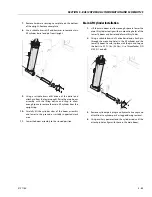
Tag and disconnect the slave cylinder hydraulic hoses.
Cap hoses to prevent the hydraulic system from being
contaminated.
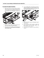
6.
Properly secure the slave cylinder by using a suitable
sling or support.
NOTE:
The Slave cylinder weighs approximately 77.15 lbs. (35 kg).
7.
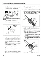
Remove the slave cylinder pin retaining hardware. Using
a suitable brass drift, remove the slave cylinder pins
from the rod and barrel ends.
8.
Carefully remove the slave cylinder.
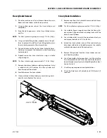
9.
Clean and inspect the cylinder pins and retaining hard-
ware for reuse. Replace if necessary.
Slave Cylinder Installation
1.
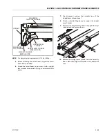
Remove caps from the hydraulic hoses and attach hoses
to the proper cylinder ports.
NOTE:
The Slave cylinder weighs approximately 77.15 lbs. (35 kg).
2.
Use suitable slings or support to position the Slave cylin-
der in place. Align barrel end mounting holes with the
holes in main fly boom.
3.
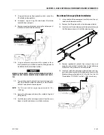
Use suitable mallet to install the barrel end attach pin
and torque the bolts to 35 ft. lbs. (48 Nm).
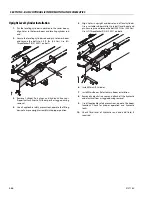
4.
Extend the slave cylinder rod until the rod attach pin
hole aligns with holes in the platform pivot. Use suitable
mallet and keeper to install the rod end pin.
5.
Remove lifting device from the slave cylinder and sup-
port from the platform.
6.
Use all applicable safety precautions, start the machine
from the ground control. Fully raise and lower the main
boom through several cycles to bleed the platform level
hydraulic circuit.
7.
Check for proper operation and hydraulic leaks.
8.
Check the fluid level of hydraulic tank. Fill the tank, if
required.
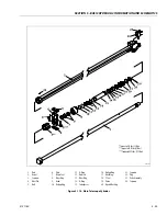
SLAVE CYLINDER
Summary of Contents for 740AJ
Page 2: ......
Page 55: ...SECTION 3 CHASSIS TURNTABLE 3121160 3 3 This page left blank intentionally...
Page 116: ...SECTION 3 CHASSIS TURNTABLE 3 64 3121160 Figure 3 44 Swing Hub Prior to SN 0300074383...
Page 203: ...SECTION 3 CHASSIS TURNTABLE 3121160 3 151 Figure 3 77 EFI Component Location...
Page 206: ...SECTION 3 CHASSIS TURNTABLE 3 154 3121160 Figure 3 78 ECM EPM Identification ECM EPM...
Page 224: ...SECTION 3 CHASSIS TURNTABLE 3 172 3121160 Figure 3 83 Deutz EMR 2 Troubleshooting Flow Chart...
Page 228: ...SECTION 3 CHASSIS TURNTABLE 3 176 3121160 Figure 3 87 EMR 2 Engine Plug Pin Identification...
Page 229: ...SECTION 3 CHASSIS TURNTABLE 3121160 3 177 Figure 3 88 EMR 2 Vehicle Plug Pin Identification...
Page 230: ...SECTION 3 CHASSIS TURNTABLE 3 178 3121160 Figure 3 89 EMR2 Fault Codes Sheet 1 of 5...
Page 231: ...SECTION 3 CHASSIS TURNTABLE 3121160 3 179 Figure 3 90 EMR2 Fault Codes Sheet 2 of 5...
Page 232: ...SECTION 3 CHASSIS TURNTABLE 3 180 3121160 Figure 3 91 EMR2 Fault Codes Sheet 3 of 5...
Page 233: ...SECTION 3 CHASSIS TURNTABLE 3121160 3 181 Figure 3 92 EMR2 Fault Codes Sheet 4 of 5...
Page 234: ...SECTION 3 CHASSIS TURNTABLE 3 182 3121160 Figure 3 93 EMR2 Fault Codes Sheet 5 of 5...
Page 303: ...SECTION 4 BOOM PLATFORM 3121160 4 31 Figure 4 20 Rotator Assembly HELAC...
Page 460: ...SECTION 5 BASIC HYDRAULIC INFORMATION AND SCHEMATICS 5 116 3121160 NOTES...
Page 467: ...SECTION 6 JLG CONTROL SYSTEM 3121160 6 7 Figure 6 2 ADE Block Diagram...
Page 534: ...SECTION 6 JLG CONTROL SYSTEM 6 74 3121160 NOTES...
Page 580: ...SECTION 7 BASIC ELECTRICAL INFORMATION SCHEMATICS 7 46 3121160 NOTES...
Page 581: ......

