background image

in

fo

@

n

if

ty

li

ft

.c

o

m

.com

Track

Drive

Operating & Safety Instructions

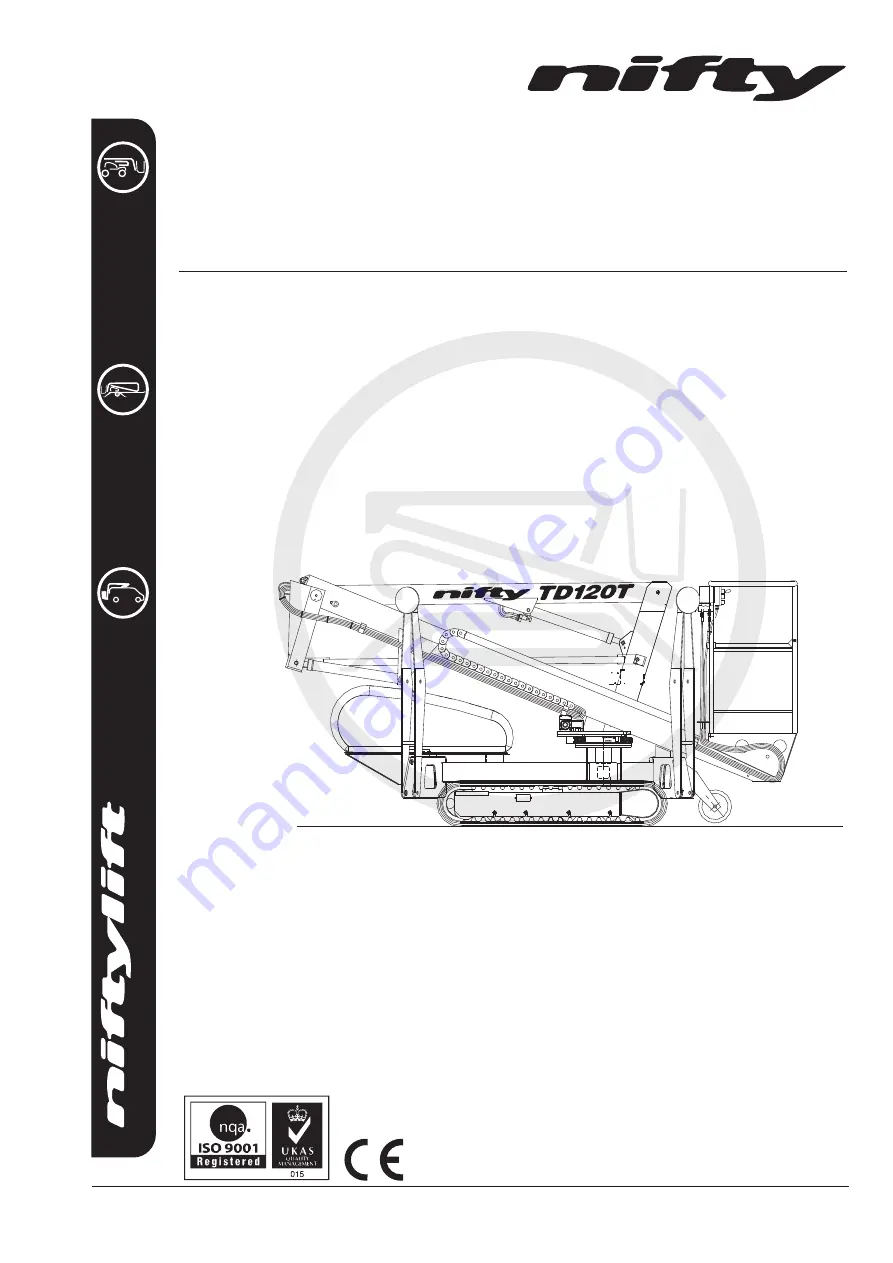
MODEL TD120T/TD34T SERIES

Manufactured by:

Niftylift Limited

Chalkdell Drive

Shenley Wood

Milton Keynes

MK5 6GF

England

www.niftylift.com

e-mail: [email protected]

Tel: +44 (0)1908 223456

Fax: +44 (0)1908 312733

M50261/0

6

Summary of Contents for TrackDrive TD120T Series

Page 1: ...Operating Safety Instructions MODEL TD120T TD34T SERIES Manufactured by Niftylift Limited Chalkdell Drive Shenley Wood Milton Keynes MK5 6GF England www niftylift com e mail info niftylift com Tel 44...

Page 2: ......

Page 3: ...n for Use 12 3 3 Pre Operational Safety Check Schedules 13 14 3 4 Placard Decals and Installation 15 17 3 5 Torque Requirements 18 4 OPERATION 4 1 Overview 19 25 4 2 Setting Up Procedures 26 4 3 Groun...

Page 4: ...strictly forbidden One of the most important facts to remember is that any equipment is only as safe as those who operate it DANGER WARNING CAUTION IMPORTANT INSTRUCTIONS AND NOTICE Any place these t...

Page 5: ...8836 Nifty Pty Ltd 11 Kennington Drive Tomago NSW 2322 Australia Tel 61 0 2 4964 9765 Fax 61 0 2 4964 9714 The Niftylift TD120T Track Drive is an extremely versatile articulated boom platform of uniq...

Page 6: ...3 55m 11ft 8in MAXIMUM LENGTH STOWED 3 95m 12ft 11in MAXIMUM CAPACITY EUROPEAN USA 200kg 440lbs 500lb TURRET ROTATION 406 TURRET TAIL SWING Zero MAXIMUM TRAVEL SPEED 1 04 mph High 1 67 kph 0 62 mph Lo...

Page 7: ...ty Instructions English USA 02 17 5 1 5 IDENTIFICATION UK PLATE This manufacturer s plate is attached to Boom 1 on each machine at the time of manufacture on every Niftylift Please ensure all sections...

Page 8: ...TrackDrive TD Series Operating Safety Instructions English USA 02 17 6 1 6 EC DECLARATION OF CONFORMITY Typical...

Page 9: ...Instructions for that model 2 1 3 Before use each day and at the beginning of each shift the Niftylift shall be given a visual inspection and functional test including but not limited to operating and...

Page 10: ...t attempt to increase your height or reach by standing and or climbing on the platform guardrails or any other object KEEP YOUR FEET ON THE PLATFORM FLOOR Do not sit stand or climb on the guardrail mi...

Page 11: ...ition relating to capacity intended use or safe operation he shall cease operation of the Niftylift and request further information as to safe operation from his management or owner dealer or manufact...

Page 12: ...persons in the cage must take suitable precautions to prevent items falling or being ejected from the cage E g Tethering tools to the machine or operator if practical and an assessment of any resultin...

Page 13: ...exhibit significantly lower emissions than this figure dependant on power option In normal operation the Vibration level to which the operator is subjected will not exceed a weighted root mean square...

Page 14: ...aerial platform Carry out the Pre operational Report before placing machine in service 3 2 PREPARATION FOR USE Whilst every effort has been made at the Niftylift factory to ensure your machine arrive...

Page 15: ...ck that operating buttons and emergency stop buttons function properly 9 Check the operation of the manual hand pump 10 Visually inspect all hydraulic hoses and fittings for damage or leaks 11 Check o...

Page 16: ...place 8 Lightly oil the jack pad ball joints and outrigger housings 9 Check and adjust if necessary the Nylatron studs around the telescope boom 10 Every three months check and verify the calibration...

Page 17: ...1 1 9 Machine Plate P15383 1 10 Cage Gate Warning P18432 1 11 IPAF training P22055 1 12 Crush Hazard P14782 8 13 Diesel Fuel Only P14414 1 14 Point Load 13kN P14965 4 15 Hydraulic Controls Cage P14927...

Page 18: ...nd USA P24893 1 35 Operating Instructions P14892 1 36 Safe Cage Entry USA P18192 1 37 Noise Warning 85dB P17124 1 38 Daily Safety Check List P14908 1 39 Tie Down Point P14958 4 40 Cage tie down warnin...

Page 19: ...TrackDrive TD Series Operating Safety Instructions English USA 02 17 17...

Page 20: ...ns 1 Bolts to ISO 898 1 Mechanical properties of fasteners made of carbon steel and alloy steel 2 For unplated bolts all grades Hex head bolts Black oxide steel bolt with a rolled oiled thread no fini...

Page 21: ...tion then the outrigger sensors are active and would warn the operator of an unsafe condition should one of them loose contact with the ground These control functions are of primary importance to safe...

Page 22: ...cks Cold starting the engine See section 4 3 1 is permissible from the side of the canopy and once running all controls are situated at the head of the lowest boom If the machine is to be used in an e...

Page 23: ...from the platform mounted footswitch controlling both the engine speed and the drive pump dump valve for increased safety 4 1 4 RAMPS AND INCLINES The ability of the Track Drive machine to ascend and...

Page 24: ...ARIABLE WIDTH TRACK OPTION On machines fitted with variable width tracks i e the Light weight version of the Track Drive machines it is recommended that whenever the machine is driven across a slope o...

Page 25: ...diverts flow to the outrigger circuit and at the same time energises the boom jack dump valve If high throttle is selected the engine will go to high revs allowing the four outriggers to be deployed...

Page 26: ...levers also become isolated The machine can now be manoeuvred through its entire working envelope allowing both operators to ascend to a working height of 12 2 metres and an outreach of 6 1 metres The...

Page 27: ...t is always recommended to evaluate the nature of the emergency before recovery is attempted and if appropriate the machine can be moved to limit the projection of the booms in the prohibited directio...

Page 28: ...ey switch at the ground control station is turned to the ON position i e clockwise 8 From the platform control station turn the Duty Selector switch clockwise to Outriggers whilst pressing the platfor...

Page 29: ...120T will automatically default to the primary power source usually mains AC PETROL GASOLINE ENGINE OR PETROL GASOLINE ELECTRIC MODELS 8 For a cold engine start go to step 9 or for a warm engine start...

Page 30: ...1 2 3 4 B Select lever 1 2 3 or 4 for desired boom function 1 Operates Telescope UP for out DOWN for in 2 Operates Lower Boom UP for up DOWN for down 3 Operates Upper Boom UP for up DOWN for down 4 Op...

Page 31: ...nd put the key in the platform control station and switch to ON clockwise 5 Battery electric models go to step 11 DIESEL ENGINE OR Bl ENERGY MODELS ONLY 6 Ensure that the main engine ignition switch i...

Page 32: ...or Base PLATFORM CONTROL STATION 1 Emergency Stop Button Push to operate twist knob to re set to the Out position 2 Horn Operates audible alarm 3 Tilt Alert Illuminates when excess drive angle is det...

Page 33: ...Telescope UP for out DOWN for in 3 Operates Lower Boom UP for up DOWN for down 4 Operates Upper Boom UP for up DOWN for down 5 Operates Swing UP for right DOWN for left IF ALARM SOUNDS DESCEND IMMEDI...

Page 34: ...be disabled until the load is reduced to below 95 of the safe working limit The design of the unit meets the requirements of both BS EN280 and ISO 13849 with a safety integrity level of Category 3 PL...

Page 35: ...hat creepage during transport does not permit the machine to come into contact with other goods being shipped or the container itself Some movement of the machine structure might occur during transit...

Page 36: ...asional top up charge of the batteries will serve to equalise their charge level 3 Leave diesel engine switch in the OFF position to prevent discharge of batteries through leakage 4 If machine is to b...

Page 37: ...usly operating the lever and green button to move the cage Take care not to become trapped between the moving cage and a fixed object and ensure those around you are clear of the moving cage When the...

Page 38: ...This is then the fastest method of lowering the platform to the ground Note If the machine is fitted with a cage overload system and the cage comes into contact with a fixed object whilst operating a...

Page 39: ...occurs it shall be the responsibility of the seller to notify Niftylift direct of the unit model and serial number and the name and address of the new owner within 60 days This important step is requ...

Page 40: ...ge Wheel bearings OK Cylinders are silent Platform is level over full range Booms levelling rods not damaged or distorted Booms levelling rods cylinders not fouling Hoses not tight kinked or fouled Op...

Page 41: ...and terminals secure All hose connections secure Hoses not kinked or fouled Charger control box secure Battery secure Electrolyte level and specific gravity Hydraulic oil level Engine Gear box oil FI...

Page 42: ...ts to the category selected and any fault exclusions The stabiliser monitoring is only active when the booms are lifted up off the boom rest such that the boom switch is actuated The boom switch relie...

Page 43: ...channel will cause the circuit to halt operation 5 Response time The monitoring of the stabilisers is active at all times providing the security of the outrigger feet being in contact with the ground...

Page 44: ...ment only replace the complete item such as Boom Switch Jack Safety Switch PCB or Hydraulic valve block Do not attempt to open the safety module or replace components soldered to any PCB Do not attemp...

Page 45: ...itch which allows movement of the stabilisers only when the booms are stowed The boom switch relies on the electrical contacts closing allowing the jack circuit to become active Proper maintenance and...

Page 46: ...circuit There is however no alarm or indication function associated with the booms being in normal operation 8 Muting and suspension of safety functions While the stabiliser monitoring is always acti...

Page 47: ...r levelling the spine of the machine 3 At the ground control location and using the base green button raise the booms to clear the boom rest and operate the cam switch Situated between booms 2 and 3 a...

Page 48: ...ff the boom switch 2 Take a voltage reading of the electrical feed into each of the hydraulic solenoid valves from test 1 Pass Fail criteria Both channels should read 0V Any voltage greater than 0V sh...

Page 49: ...ations from the specified performance on the safety function s If the levelling system of the product does not function as intended the angle of the cage may not be maintained If the angle of cage is...

Page 50: ...of air from the hydraulic system if the product is left unused for long periods of time 11 Ease of accessibility and replacing of internal parts Replacement of parts should only be carried out by appr...

Page 51: ...interlocks or any other part of the machine Maintenance must only be carried on by appropriately trained and competent persons who are conversant with all modes of operation speeds and characteristic...

Page 52: ...polarity of components if applicable Diode outputs etc Only Niftylift original and supplied parts shall be used 12 Means for easy and safe trouble shooting To check the operation of the load sensor sy...

Page 53: ...riately trained and competent persons 3 The effects of deviations from the specified performance on the safety function s If the load holding system of the product does not function as intended the an...

Page 54: ...rom the hydraulic system if the product is left unused for long periods of time 11 Ease of accessibility and replacing of internal parts Replacement of parts should only be carried out by appropriatel...

Page 55: ......

Reviews: