Fuji Electric FRENIC-Ace series User Manual Download Page 695


12.1 Standard Model 


12-3 


SP

EC

IF

IC

AT

IO

N

S


Chap 1


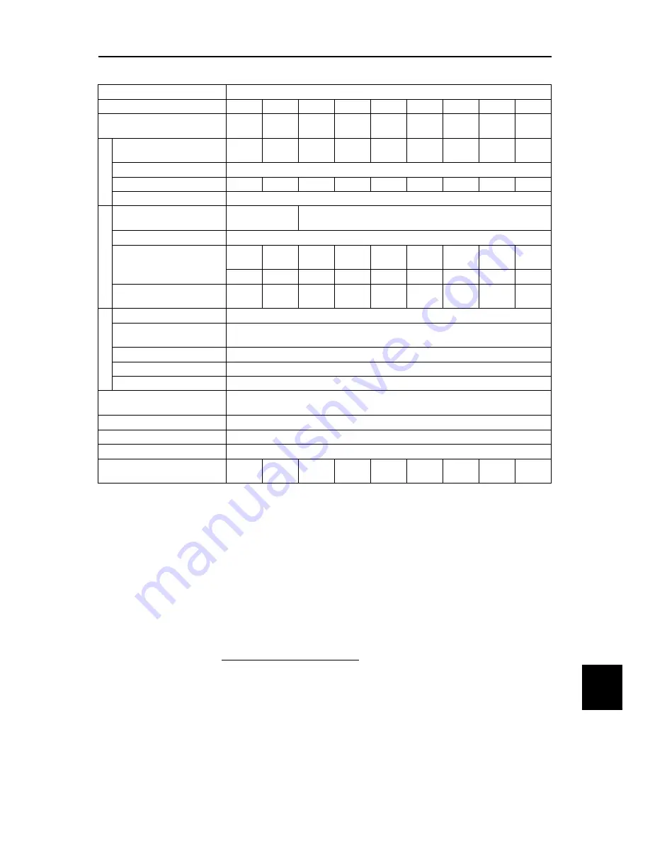
Standard-model, Three-phase 400 V (460 V) class series (ND-mode: 75 kW to 315 kW) 

Item 

Specifications 

Type (FRN_ _ _ _E2S-4

0139 

0168 

0203 

0240 

0290 

0361 

0415 

0520 

0590 

Nominal applied motor (kW) [HP] 

(Output rating) 

*1


75 

[100] 

90 

[125] 

110 

[150] 

132 

[200] 

160 

[200] 

200 

[300] 

220 

[350] 

280 

[450] 

315 

[500] 

O

utput r

ati

ngs


Rated capacity (kVA) 

*2


106 

[111] 

128 

[134] 

155 

[162] 

183 

[191] 

221 

[231] 

275 

[288] 

316 

[331] 

396 

[414] 

450 

[470] 

Rated voltage (V) 

*

3

  Three-phase 380 to 480 V (with AVR function) 

Rated current (A) 

*

4


139 

168 

203 

240 

290 

361 

415 

520 

590 

Overload capability 

120%-1 min  

Input powe

Voltage, frequency 

Three-phase 380 

to 480 V, 50/60 Hz 

Three-phase 380 to 440 V, 50 Hz 

Three-phase 380 to 480 V, 60 Hz 

*5


Allowable voltage/frequency 

Voltage: +10 to -15% (Interphase voltage unbalance: 2% or less) 

*6

, Frequency: +5 to -5% 

Rated input current 

*7


(w/o DCR) (A) 


– 

– 

– 

– 

– 

– 

– 

– 

– 

(with DCR) (A) 


138 

164 

201 

238 

286 

357 

390 

500 

559 

Required capacity 

(with DCR) (kVA) 

*8


96 

114 

139 

165 

199 

248 

271 

347 

388 

B

rak

ing 

Torque (%) 

*9


5% to 9% 

DC braking 

Braking starting frequency: 0.0 to 60.0 Hz, Braking time: 0.0 to 30.0 s, 

Braking level: 0 to 60% 

Braking transistor 

Separately mounted option 

Minimum resistance value


(

Ω

)  – 

Braking resistor 

Separately mounted option 

DC reactor (DCR) 

Must be used. Separately mounted component. Depending on the shipping destination, not 

provided with the inverter package.  

*11


Applicable safety standards 

IEC/EN61800-5-1: 2007 

Enclosure (IEC60529) 

IP00, UL open type 

Cooling method 

Fan cooling 

Weight / Mass (kg) [lbs] 

30 

[66] 

33 

[73] 

40 

[88] 

62 

[137] 

63 

[139] 

95 

[209] 

96 

[212] 

130 

[287] 

140 

[309] 


Note: A box (

) in the above table replaces GA, GB or C depending on the model. 

*1  Fuji 4-pole standard motor 
*2  Rated capacity is calculated assuming the rated output voltage as 440 V (460 V). 
*3  Output voltage cannot exceed the power supply voltage. 
*4  Setting the carrier frequency (F26) to the following value or above requires current derating. 

ND spec. of all types : 4 kHz 

If the ambient temperature is 40°C (104°F) or above, derating of 2%/°C (2%/1.8°F) relative to the rated 

current given in this manual is required. For details, refer to Figure 10.4-1 in Chapter 10 “10.4.2 Guideline for 

selecting inverter drive mode and capacity.” 

*5 

Inverters of FRN0203E2■

-4

 or above (400 V class series) are equipped with a power switching connector. 

Use the connector depending upon the applied voltage. For details, refer to  Chapter 2  “2.2.7 Switching 

Connector.” 

*6 

67


×


(V)


voltage


average


phase

-

Three

(V)


voltage


Min.

 -


(V)


voltage


Max.

=

(%)


unbalance


Voltage

 (IEC 61800-3) 

If the unbalance ratio is 2% to 3%, use an optional AC reactor (ACR). 

*7  This specification is an estimated value to be applied when the power supply capacity is 500 kVA (Inverter 

capacity × 10 when the capacity exceeds 50 kVA) and the power supply with %X = 5% is connected. When 

applying with motors of 75 kW (100 HP) or above, a DC reactor (DCR) should be used. 

*8  This specification applies when a DC reactor (DCR) is used. 
*9  Average braking torque for the motor running alone. It depends on the efficiency of the motor. 
*11  Please consult your Fuji Electric sales representative. 
 

Summary of Contents for FRENIC-Ace series

Page 1: ...ination setting This product is designed to drive a three phase motor under variable speed control Read through this user s manual and become familiar with the handling procedure for correct use Impro...

Page 2: ...ed herein is subject to change without prior notice for improvement The purpose of this user s manual is to provide accurate information in handling setting up and operating of the FRENIC Ace series o...

Page 3: ...lists the other materials related to the use of the FRENIC Ace Read them in conjunction with this manual if necessary Name Material No Description Catalog 24A1 E 0042 Product scope features specificat...

Page 4: ...nspection items of the inverter Chapter 8 BLOCK DIAGRAMS FOR CONTROL LOGIC This chapter describes the main block diagrams of the control section Chapter 9 COMMUNICATION FUNCTIONS This chapter describe...

Page 5: ...M 1 10 INSTALLATION AND WIRING Chapter 2 2 1 Installation 2 1 2 2 Wiring 2 3 2 2 1 Basic connection diagram 2 3 2 2 2 Removal and attachment of the front cover terminal cover and wiring guide 2 6 2 2...

Page 6: ...ting a Desired Motor Drive Control 4 8 4 6 1 V f control with slip compensation inactive for IM 4 8 4 6 2 Vector control without speed sensor Dynamic torque vector for IM 4 8 4 6 3 V f control with sl...

Page 7: ...UP DOWN F01 7 5 54 4 Frequency setting using digital inputs option DIO interface card F01 11 5 55 5 Frequency setting using pulse train input F01 12 5 55 5 3 2 E codes Extension terminal functions 5 1...

Page 8: ...24 lu Undervoltage 6 15 25 0cn Instantaneous overcurrent 6 16 26 0h1 Cooling fin overheat 6 17 27 0h2 External alarm 6 17 28 0h3 Inverter internal overheat 6 17 29 0h4 Motor protection PTC thermistor...

Page 9: ...k bus capacitor under ordinary operating conditions 7 8 3 Early warning of lifetime alarm 7 8 7 5 Measurement of Electrical Amounts in Main Circuit 7 9 7 6 Insulation Test 7 10 7 7 Inquiries about Pro...

Page 10: ...nverter 9 17 3 Transmit PDO from inverter to master 9 19 4 Communication parameters of receive PDO 9 20 5 Communication parameters of transmit PDO 9 21 6 Changing PDO RPDO TPDO mapping entry 9 22 9 2...

Page 11: ...alculating the RMS rating of the motor 10 14 10 4 Selecting an Inverter Drive Mode ND HD HND HHD 10 15 10 4 1 Precaution in making the selection 10 15 10 4 2 Guideline for selecting inverter drive mod...

Page 12: ...11 68 11 23 Analog interface card OPC AIO 11 70 11 24 RS 485 communication card OPC E2 RS 11 73 11 25 PG interface card OPC E2 PG3 11 75 11 25 1 Interface specifications feedback side PG interface 11...

Page 13: ...ples 8 Appendix B Japanese Guideline for Suppressing Harmonics by Customers Receiving High Voltage or Special High Voltage General purpose inverter 12 B 1 Application to general purpose inverters 12 1...

Page 14: ...pliance with EMC standards 26 2 Compliance with the low voltage directive in the EU 31 G 2 Harmonic Component Regulation in the EU 38 1 General comments 38 2 Compliance with the harmonic component reg...

Page 15: ...directly related to the human safety Though the FRENIC Ace is manufactured under strict quality control install safety devices for applications where serious accidents or property damages are foresee...

Page 16: ...could occur Be sure to perform wiring after installing the inverter unit Otherwise an electric shock or injuries could occur Ensure that the number of input phases and the rated voltage of the product...

Page 17: ...nfigures the function codes wrongly without completely understanding this User s Manual the motor may rotate with a torque or at a speed not permitted for the machine Starting auto tuning involves mot...

Page 18: ...result in malfunction or damage and an accident or fire could occur Contact outputs 30A B C use relays and may remain ON OFF or undetermined when their lifetime is reached In the interests of safety e...

Page 19: ...tor correction 1 8 2 Power supply lines Application of a DC AC reactor 1 8 3 DC reactor DCR for correcting the inverter input power factor for suppressing harmonics 1 8 4 PWM converter for correcting...

Page 20: ......

Page 21: ...of FRN0203E2 4G or above Not included with the FRN E2 4C china model Keypad rear cover with three screws for securing the keypad Instruction manual CD ROM containing the FRENIC Ace User s Manual 2 The...

Page 22: ...hree phase 3PH input voltage input frequency input current OUTPUT Number of output phases rated output voltage output frequency range rated output capacity rated output current and overload capability...

Page 23: ...ng plate Main nameplate Main circuit terminal block Warning label Keypad enclosure can be opened Internal air circulation fan Cooling fans Main nameplate Keypad Front cover Warning plate Front cover C...

Page 24: ...1 2 External View and Terminal Blocks 1 4 2 Warning plates and label a FRN0006E2 4G b FRN0203E2 4G Figure 1 2 2 Warning Plates and Label...

Page 25: ...000 m 3 300 ft max Note 3 Atmospheric pressure 86 to 106 kPa Vibration FRN0115E2 2 or below FRN0203E2 4 or below FRN0011E2 7 or below FRN0240E2 4 or above 3 mm Max amplitude 2 to less than 9 Hz 3 mm...

Page 26: ...presses combustors and industrial waste treatment A lot of fibrous or paper dust Fibrous or paper dust accumulated on the heat sink lowers the cooling effect Entry of dust into the inverter causes the...

Page 27: ...t satisfy the specified requirements listed in Table 1 3 3 wrap the inverter in an airtight vinyl sheet or the like for storage 3 If the inverter is to be stored in a high humidity environment put a d...

Page 28: ...their peak levels increase These factors may break rectifiers or capacitors in the converter section of the inverter or decrease the capacitance of the capacitors If the input voltage unbalance rate...

Page 29: ...s down the magnetic contactor MC in the inverter input circuit with an alarm output signal ALM issued on inverter s programmable output terminals The sequence minimizes the secondary damage even if th...

Page 30: ...put current harmonics resulting in demagnetization When decreasing the carrier frequency setting be sure to check the allowable carrier frequency of the motor 1 3 5 Leakage current A high frequency cu...

Page 31: ...layout diagram main circuit terminal 2 15 3 Recommended wire size main circuit terminals 2 17 4 Description of terminal functions main circuit terminal 2 38 2 2 6 Control circuit terminals common to a...

Page 32: ......

Page 33: ...e below 40 C only the units can be installed side by side without any spacing between them 30 C or lower for ND and HD Table 2 1 1 Surrounding Space mm inch Applicable Capacity A B C 200 V class FRN00...

Page 34: ...the case attachment screws on the top of the inverter 2 Fix the mounting bases to the case attachment screw holes using the mounting base fixation screws A few screws should remain after changing the...

Page 35: ...2 2 Wiring 2 3 INSTALLATION AND WIRING Chap 2 2 2 Wiring 2 2 1 Basic connection diagram Model GA Standard terminal block board with CAN Figure 2 2 1 Standard Terminal Block Board with CAN Note 16...

Page 36: ...2 2 Wiring 2 4 Model GB Model C Standard terminal block board without CAN with FM2 Figure 2 2 2 Standard Terminal Block Board Without CAN With FM2 Note 16...

Page 37: ...d exists in the same power system Note 6 Types FRN0011E2 7 FRN0115E2 2 FRN0072E2 4 or below have built in braking transistors allowing direct connection of braking resistors between P DB Note 7 When c...

Page 38: ...f the terminal cover and then pull it up toward you 2 Pull out the wiring guide toward you 3 After routing the wires attach the wiring guide and the terminal cover reversing the steps above Figure 2 2...

Page 39: ...emoval of the Front Cover and the Wiring Guide for FRN0072E2 4 4 Types FRN0085E2 4 or above 1 Loosen the screws of the front cover Hold both sides of the front cover with the hands and slide it upward...

Page 40: ...ate the routing of the lines connected to the main circuit input side terminals primary side and the output side terminals secondary side and the lines connected to the control circuit terminals The c...

Page 41: ...routing space Be warned that removing the wiring guide to accommodate the enlarged main circuit wiring will result in non conformance to IP20 requirements Figure 2 2 7 Wiring Guide FRN0069E2 2 Figure...

Page 42: ...m 328ft Power supply Inverter Motor Below 400 m 1312ft Below 5 m 16ft Output circuit filter When the output circuit filter is used the total wiring length should be below 400 m 1312ft in case of using...

Page 43: ...utput side secondary side Risk of fire exists Ground the inverter in compliance with the national or local electric code Always connect the ground line to the inverter grounding terminal zG Risk of el...

Page 44: ...m lb in Three phase 200 V FRN0001E2S 2 Fig a M3 5 0 8 7 1 M3 5 1 2 10 6 FRN0002E2S 2 FRN0004E2S 2 FRN0006E2S 2 FRN0010E2S 2 Fig b M4 1 2 10 6 M4 1 8 15 9 FRN0012E2S 2 FRN0020E2S 2 Fig c FRN0030E2S 2 F...

Page 45: ...361E2S 4 Fig G M12 48 425 M10 27 239 FRN0415E2S 4 FRN0520E2S 4 Fig H FRN0590E2S 4 Table 2 2 4 Screw Specifications Three phase 400V series EMC filter built in type Power System Inverter type See item...

Page 46: ...FRN0002E2S 7 FRN0003E2S 7 FRN0005E2S 7 FRN0008E2S 7 Fig l M4 1 2 10 6 M4 1 8 15 9 FRN0011E2S 7 Fig m Table 2 2 6 Screw Specifications Single phase 200V series EMC filter built in type Power System Inv...

Page 47: ...igh voltage when power is ON Main circuit L1 R L2 S L3 T L1 L L2 N P1 P N DB U V W R0 T0 R1 T1 Insulation level Main circuit Casing Basic insulation overvoltage category III degree of contamination 2...

Page 48: ...0 35 9 0 35 9 0 35 9 0 35 9 0 35 9 0 35 10 17 0 40 L1 R L3 T L2 S P1 P N DB U V W 9 0 35 9 0 35 9 0 35 9 0 35 9 0 35 9 0 35 9 0 35 10 0 39 10 0 39 10 0 39 10 17 0 40 10 17 0 40 6 7 0 26 6 8 0 27 P1 P...

Page 49: ...en smaller than the IV wire or the HIV wire and also more flexible Due to these features the wire is used to reduce the area occupied by wiring and to improve work efficiency in high temperature areas...

Page 50: ...300 150 2 220 FRN0415E2 4 300 150 150 2 185 2 280 FRN0520E2 4 185 2 185 240 2 300 2 315 FRN0590E2 4 240 2 240 240 2 300 2 HD Mode Conforming to low voltage directive in Europe Power System Std Applica...

Page 51: ...e directive in Europe Power System Std Applicable Motor kW Inverter type Recommended wire size mm 2 Main power supply input L1 R L2 S L3 T Ground terminal zG Inverter output U V W For DC reactor conne...

Page 52: ...FRN0415E2 4 38 280 FRN0520E2 4 38 315 FRN0590E2 4 60 HD Mode Ambient temperature Below 40 C Wire type 60 C wire Power System Std Applicable Motor kW Inverter type Recommended wire size mm 2 Main powe...

Page 53: ...2 Three phase 400 V 0 75 FRN0002E2 4 2 2 2 2 2 2 1 1 FRN0004E2 4 2 2 2 2 2 2 2 2 FRN0006E2 4 2 2 2 2 2 2 3 0 FRN0007E2 4 10 2 2 2 2 2 2 5 5 FRN0012E2 4 10 2 2 2 2 2 2 7 5 FRN0022E2 4 2 3 5 2 2 2 2 11...

Page 54: ...115E2 2 22 38 7 8 22 38 7 2 Three phase 400 V 0 4 FRN0002E2 4 2 2 2 2 2 2 0 75 FRN0004E2 4 2 2 2 2 2 2 1 5 FRN0006E2 4 2 2 2 2 2 2 2 2 FRN0007E2 4 2 2 2 2 2 2 3 7 FRN0012E2 4 2 2 2 2 2 2 5 5 FRN0022E2...

Page 55: ...00 280 FRN0520E2 4 200 38 250 325 315 FRN0590E2 4 250 60 250 325 HD Mode Ambient temperature Below 40 C Wire type 75 C wire Power System Std Applicable Motor kW Inverter type Recommended wire size mm...

Page 56: ...hree phase 400 V 0 75 FRN0002E2 4 2 2 2 2 2 2 1 1 FRN0004E2 4 2 2 2 2 2 2 2 2 FRN0006E2 4 2 2 2 2 2 2 3 0 FRN0007E2 4 10 2 2 2 2 2 2 5 5 FRN0012E2 4 10 2 2 2 2 2 2 7 5 FRN0022E2 4 2 2 2 2 2 2 11 FRN00...

Page 57: ...4 2 2 2 2 2 2 0 75 FRN0004E2 4 2 2 2 2 2 2 1 5 FRN0006E2 4 2 2 2 2 2 2 2 2 FRN0007E2 4 2 2 2 2 2 2 3 7 FRN0012E2 4 2 2 2 2 2 2 5 5 FRN0022E2 4 2 2 2 2 2 2 7 5 FRN0029E2 4 2 2 2 2 2 2 11 FRN0037E2 4 2...

Page 58: ...50 38 200 250 315 FRN0590E2 4 200 60 200 250 HD Mode Ambient temperature Below 40 C Wire type 90 C wire Power System Std Applicabl e Motor kW Inverter type Recommended wire size mm 2 Main power supply...

Page 59: ...14 22 22 2 Three phase 400 V 0 75 FRN0002E2 4 2 2 2 2 2 2 1 1 FRN0004E2 4 2 2 2 2 2 2 2 2 FRN0006E2 4 2 2 2 2 2 2 3 0 FRN0007E2 4 10 2 2 2 2 2 2 5 5 FRN0012E2 4 10 2 2 2 2 2 2 7 5 FRN0022E2 4 2 2 2 2...

Page 60: ...75 FRN0004E2 4 2 2 2 2 2 2 1 5 FRN0006E2 4 2 2 2 2 2 2 2 2 FRN0007E2 4 2 2 2 2 2 2 3 7 FRN0012E2 4 2 2 2 2 2 2 5 5 FRN0022E2 4 2 2 2 2 2 2 7 5 FRN0029E2 4 2 2 2 2 2 2 11 FRN0037E2 4 2 2 3 5 2 2 2 15 F...

Page 61: ...Mode Ambient temperature Below 50 C Wire type 60 C wire Power System Std Applicable Motor kW Inverter type Recommended wire size mm 2 Main power supply input Note 1 L1 R L2 S L3 T Ground terminal Not...

Page 62: ...2 4 2 5 5 2 3 5 3 5 2 11 FRN0029E2 4 5 5 8 3 5 5 5 5 5 2 15 FRN0037E2 4 8 14 3 5 8 14 2 18 5 FRN0044E2 4 14 22 5 5 14 14 2 22 FRN0059E2 4 14 22 5 5 14 22 2 30 FRN0072E2 4 22 38 8 1 22 38 2 37 FRN0085E...

Page 63: ...5 2 11 FRN0037E2 4 5 5 8 3 5 5 5 5 5 2 15 FRN0044E2 4 8 14 5 5 8 14 2 18 5 FRN0059E2 4 14 22 5 5 14 14 2 22 FRN0072E2 4 14 22 5 5 14 22 2 30 FRN0085E2 4 22 38 8 22 38 37 FRN0105E2 4 38 60 8 38 38 45...

Page 64: ...temperature Below 50 C Wire type 75 C wire Power System Std Applicable Motor kW Inverter type Recommended wire size mm 2 Main power supply input Note 1 L1 R L2 S L3 T Ground terminal Note 1 zG Inverte...

Page 65: ...2 2 2 2 2 2 3 0 FRN0007E2 4 10 2 2 2 2 2 2 5 5 FRN0012E2 4 10 2 2 2 2 2 2 7 5 FRN0022E2 4 2 2 2 2 2 2 11 FRN0029E2 4 2 3 5 3 5 2 3 5 2 15 FRN0037E2 4 3 5 5 5 3 5 5 5 5 5 2 18 5 FRN0044E2 4 5 5 8 5 5 5...

Page 66: ...2 2 2 2 2 2 2 FRN0007E2 4 2 2 2 2 2 2 3 7 FRN0012E2 4 2 2 2 2 2 2 5 5 FRN0022E2 4 2 2 2 2 2 2 7 5 FRN0029E2 4 2 2 2 2 2 2 11 FRN0037E2 4 2 3 5 3 5 2 3 5 2 15 FRN0044E2 4 3 5 5 5 5 5 3 5 5 5 2 18 5 FR...

Page 67: ...urrent x 80 Recommended wire sizes assume these conditions HD Mode Ambient temperature Below 50 C Wire type 90 C wire Power System Std Applicable Motor kW Inverter type Recommended wire size mm 2 Main...

Page 68: ...ee phase 400 V 0 75 FRN0002E2 4 2 2 2 2 2 2 1 1 FRN0004E2 4 2 2 2 2 2 2 2 2 FRN0006E2 4 2 2 2 2 2 2 3 0 FRN0007E2 4 10 2 2 2 2 2 2 5 5 FRN0012E2 4 10 2 2 2 2 2 2 7 5 FRN0022E2 4 2 2 2 2 2 2 11 FRN0029...

Page 69: ...E2 4 2 2 2 2 2 2 0 75 FRN0004E2 4 2 2 2 2 2 2 1 5 FRN0006E2 4 2 2 2 2 2 2 2 2 FRN0007E2 4 2 2 2 2 2 2 3 7 FRN0012E2 4 2 2 2 2 2 2 5 5 FRN0022E2 4 2 2 2 2 2 2 7 5 FRN0029E2 4 2 2 2 2 2 2 11 FRN0037E2 4...

Page 70: ...power supply Types FRN0088E2 4 FRN0059E2 4 or above R1 T1 Auxiliary power input for fan Ordinarily these terminals do not need to be connected Connect these terminals to AC power supply when operatin...

Page 71: ...terminals P1 P Types FRN0203E2 4 or above will not have the shorting bar connected 2 Connect the P1 P terminals to the direct current reactor option Keep the wiring length below 10 meters Do not remov...

Page 72: ...details such as other wirings refer to the user s manual for the braking unit Figure 2 2 9 2 Connection of other instruments The direct current intermediate circuit of other inverters and PWM converte...

Page 73: ...ng to terminals R0 T0 to the input side of the earth leakage breaker make sure that the connection is done through an insulating transformer or alternatively through the auxiliary B contacts of the ma...

Page 74: ...7 1 Table 2 2 29 Recommended Rod Terminals Screw size Wire size Type With insulating collar Without insulating collar M3 M2 0 25 mm 2 AWG24 AI 0 25 6 BU A 0 25 7 0 34 mm 2 AWG22 AI 0 34 6 TQ A 0 34 7...

Page 75: ...0 mA Max for the external frequency command potentiometer variable resistor 1 to 5 k Connect variable resistors larger than 1 2 W 12 Analog setup voltage input 1 Frequency is set up according to the e...

Page 76: ...Ai SW4 SW3 V2 C1 Figure 2 2 12 Internal circuit when SW4 is switched to PTC side Analog input monitor AI function 1 The analog input monitor can be used to monitor the status of peripheral instrument...

Page 77: ...command REV Run reverse command EN1 EN2 Enable input 1 When terminals EN1 PLC or terminals EN2 PLC are OFF the inverter output transistors stop switching safe torque off STO Be sure to operate termin...

Page 78: ...Contact When turning terminals FWD REV X1 to X5 ON and OFF using the programmable controller Figure 2 2 17 shows an example of the circuit configuration using programmable controller Circuit a in Fig...

Page 79: ...nal outputs pulse signal Signal content can be chosen same as for the FMV function by function code F31 setting The output form FMP can be switched using SW5 on the printed circuit board and function...

Page 80: ...ransistor output signals This terminal is insulated from terminals CM and 11 When connecting the programmable controller to terminals Y1 Y2 The circuit configuration example for connecting the inverte...

Page 81: ...ther devices do not use these pins RJ 45 connector for RS 485 CANopen communic a tion RS 485 communication port 2 CANopen communication port 1 Can be used to connect a computer programmable controller...

Page 82: ...h 3 8 mm 0 15inch or less in width and 1 5 mm 0 06inch or less in thickness Figure 2 2 22 Wiring Route and Fixing Position for the Control Circuit Wires Route the wiring of the control circuit termina...

Page 83: ...the receiving end with a click Power supply switching connector CN UX types FRN0203E2 4 or above This power supply switching connector CN UX is equipped on FRN0203E2 4 or above Set the connector CN U...

Page 84: ...tching Connector Positions and Figure 2 2 24 Attachment and Removal of the Switching Connector a FRN0203E2 4 to FRN0290E2 4 Setting Purpose In the case terminals R1 and T1 are NOT used Factory default...

Page 85: ...printed circuit board Figure 2 2 25 The Slide Switch Locations on the Control Printed Circuit Board To operate the slide switches remove the front cover and make the control printed circuit board visi...

Page 86: ...oltage input V2 side AI side 1 0 PTC thermistor input C1 side PTC side 0 1 SW5 Switch to change terminal FM output setting to current voltage pulse This switch changes the output type for terminal FM...

Page 87: ...urer Sanwa Supply Inc Type KB 10T5 01K for 1 meter KB STP 01K for 1 meter shielded cable when conforming to EMC directive Note 2 When attaching to the cabinet use a fixing screw of appropriate length...

Page 88: ...the hooks at the arrows and pull as shown in Figure 2 3 4 Figure 2 3 4 Removal of the Keypad 2 Attach the keypad rear cover to the keypad using the included keypad rear cover fixing screw Figure 2 3 5...

Page 89: ...and Connection of Keypad 2 57 INSTALLATION AND WIRING Chap 2 3 Cut the cabinet to attach the keypad as shown in Figure 2 3 6 Units mm inch Figure 2 3 6 Fixing Screw Positions and the Dimensions of the...

Page 90: ...the Extension Cable or the Commercially Available LAN Cable between the Keypad and the Inverter Main Body Do not connect the inverter to PC LAN ports Ethernet hubs or telephone lines The inverter and...

Page 91: ...ure 2 4 1 Figure 2 4 1 Connection of the RS 485 Communication Cable Types FRN0088E2 2GA FRN0059E2 4GA or above To connect the RS 485 communication cable open the RJ 45 cover until the click can be hea...

Page 92: ......

Page 93: ...and local modes 3 15 3 4 Programming Mode 3 16 3 4 1 Setting up function codes Data Setting f__ through o__ 3 17 3 4 2 Checking changed function codes Data Checking rep 3 18 3 4 3 Monitoring the runni...

Page 94: ......

Page 95: ...witches the inverter to Running mode In Alarm mode Pressing this key after removing the alarm factor resets the alarm and switches back to Running mode Function Data key which switches the operations...

Page 96: ...he displayed value x 10 is the actual value Example If data is 12 345 the LED monitor displays 1234 and the x10 LED lights meaning that 1 234 10 12 340 LED monitor In Running mode the LED monitor disp...

Page 97: ...LED monitor Alarm code Indicates the cause of the alarm condition For details first see Table 6 1 1 Abnormal States Detectable Heavy Alarm and Light Alarm Objects in Chapter 6 6 1 Protective Function...

Page 98: ...to select the desired one from the speed monitor items by using function code E48 2 Applicable only when PID control is active J01 1 2 or 3 3 The analog input monitor can appear only when the analog i...

Page 99: ...A Current output from the inverter in RMS 3 Input power 1 25 Hz A kW kW Input power to the inverter 9 Calculated torque 2 50 Hz A kW Motor output torque Calculated value 8 Output voltage 3 200u Hz A k...

Page 100: ...ode J01 1 2 or 3 7 When the LED monitor displays a PID command or its output amount the dot decimal point attached to the lowest digit of the 7 segment letter blinks 8 When the LED monitor displays a...

Page 101: ...actor If a light alarm occurs l al appears on the LED monitor To check the current light alarm factor enter Programming mode by pressing the key and select 5_36 on Menu 5 Maintenance Information It is...

Page 102: ...tor in the reverse direction or to run it reversibly change the data of function code F02 to 3 or 0 respectively Note The rotation direction of IEC compliant motors is opposite to the one shown above...

Page 103: ...code E64 The factory default is 0 Automatic saving when main power is turned OFF To set the reference frequency first press the key once to blink the least significant digit After that each time the...

Page 104: ...y the PID process command The lowest digit and its decimal point blink on the LED monitor 4 To change the PID process command press the key again The new setting can be saved into the inverter s inter...

Page 105: ...ode Table 3 3 4 lists the combinations of the commands Figure 3 3 1 illustrates how the manual speed command entered via the keypad is translated to the final frequency command The setting procedure i...

Page 106: ...e LED monitor 4 To change the PID dancer position set point press the key again The command you have specified will be automatically saved into the inverter s internal memory as function code J57 data...

Page 107: ...You need to switch to Running mode Table 3 3 6 lists the combinations of the commands Figure 3 3 2 illustrates how the primary frequency command entered via the keypad is translated to the final freq...

Page 108: ...me respectively Use these function codes exclusively for the jogging operation with your needs Alternatively using the input terminal command JOG Ready for jogging switches between the normal operatio...

Page 109: ...key runs the motor in the forward direction only Pressing the key stops the motor No specification of the motor rotation direction is required 2 Enable keys on keypad Forward 3 Enable keys on keypad...

Page 110: ...on functions 1 j1_ J1 codes 100s PID functions d__ d codes Application functions 2 u__ U codes Customizable logic functions u1_ U1 codes 100s Customizable logic functions y__ y codes Link functions k_...

Page 111: ...Function code data check mode Menu 2 Data Checking Menu 7 Data Copying 2 Full menu mode Menus 0 through 8 Press the key to enter Programming mode and display menus While cycling through the menus wit...

Page 112: ...everts to the previous value the display returns to the function code list and the original function code reappears 7 Press the key to return to the menu from the function code list Cursor movement Wh...

Page 113: ...he running status in Drive monitoring set function code E52 to 2 Full menu mode beforehand 1 Turn the inverter ON It automatically enters Running mode in which you press the key to switch to Programmi...

Page 114: ...ch is converted from the PID command value using function code J106 and J107 data PID display Maximum scale minimum scale Display value PID command value 100 Max scale Min scale Min scale If PID contr...

Page 115: ...CANopen built in bus status monitor For details refer to Chapter 9 9 2 16 Keypad LED operation monitor 3_41 3_42 CANopen built in DSP402 state N A Shows the transition status of the state machine defi...

Page 116: ...r control for IM with speed sensor 1011 Torque control for IM Vector control with speed sensor 10 2 9 1 8 0 Table 3 4 6 Running Status Display LED No LED4 LED3 LED2 LED1 Bit 15 14 13 12 11 10 9 8 7 6...

Page 117: ...u mode beforehand 1 Turn the inverter ON It automatically enters Running mode in which you press the key to switch to Programming mode The function selection menu appears 2 Use the and keys to display...

Page 118: ...utput current on terminal FM2 FMI2 mA Shows the output current on terminal FM2 FMI2 in milliamperes mA exclusive to Model C GB 4_10 Option control circuit terminal I O Shows the ON OFF state of the di...

Page 119: ...control Refer to Displaying control I O signal terminals under communications control on page 3 26 Displaying I O signal status in hexadecimal Each I O terminal is assigned to bit 15 through bit 0 as...

Page 120: ...however XF XR and RST are added as inputs Note that under communications control the I O display is in normal logic using the original signals not inverted For details about input commands sent throu...

Page 121: ...ulative run time Shows the content of the cumulative power ON time counter of the inverter Counter range 0 to 65 535 hours Display Upper 2 digits and lower 3 digits are displayed alternately Example 0...

Page 122: ...hen the count exceeds 65 530 the counter will be reset to 0 and start over again 5_09 Input watt hour Shows the input watt hour of the inverter Display range 001 to 9999 Input watt hour Displayed valu...

Page 123: ...ive power ON time counter of motor 1 Counter range 0 to 99 990 hours Display range 0 to 9999 the x10 LED turns ON Actual cumulative motor run time hours Displayed value x 10 When the count exceeds 99...

Page 124: ...method is the same as for 5_08 above 5_36 Light alarm factor Latest Shows the factor of the latest light alarm as an alarm code For details refer to Chapter 6 6 1 Protective Functions 5_37 Light alar...

Page 125: ...in which you press the key to switch to Programming mode The function selection menu appears 2 Use the or key to display Alarm Information al 3 Press the key to proceed to the list of alarm codes e g...

Page 126: ...over again 6_08 No of startups Shows the content of the motor startup counter i e the number of run commands issued when alarm occurred Counter range 0 to 65 530 times Display range 0 to 9999 If the c...

Page 127: ...detected speed value when alarm occurred 6_24 Running status 3 Running status 3 when alarm occurred as four hexadecimal digits For details refer to Table 3 4 14 Running Status 3 3_24 Bit Assignment gi...

Page 128: ...running status information in the keypad detach the keypad from the inverter connect it to a PC running FRENIC Loader at an office or off site place and check the inverter running status without remov...

Page 129: ...of the inverter s memory i e function code data have been partly updated and remain partly old Therefore do not operate the inverter Instead perform initialization or rewrite the entire data If this f...

Page 130: ...inverter the Enable write from keypad command WE KP is OFF A data read operation has been performed for the inverter whose data protection was enabled cper Write data error Error generated during cop...

Page 131: ...ta protection status be sure to hold the key down for at least 5 seconds Once the key is released within 5 seconds press the key to go back to the cpy display and perform the keying operation again En...

Page 132: ...codes To use Menu 0 Quick Setup you need to set function code E52 to 0 Function code data setting mode or 2 Full menu mode The predefined set of function codes that are subject to quick setup is store...

Page 133: ...is function code appears In this example data 0 of f 01 appears 5 Change the function code data using the and keys In this example press the key two times to change data 0 to 2 6 Press the key to esta...

Page 134: ...uency and output current etc by pressing the key The item number and data for each running status information will be displayed alternately Further you can view various information items on the runnin...

Page 135: ...for PMSM 4 10 4 7 Performance Comparison for Drive Controls Summary 4 11 4 8 Configuring Function Codes for Drive Controls 4 12 4 8 1 Driving an Induction Motor IM 4 13 1 Driving a non Fuji motor or F...

Page 136: ...g up a frequency command with an external potentiometer 4 30 4 10 3 Setting up a frequency command with multistep frequency selection 4 31 4 11 Selecting a Run Command Source 4 32 4 11 1 Setting up a...

Page 137: ...cable Motor Rank by F80 ND HD HND and HHD modes Power ON check Check prior to powering on Mount the inverter perform wiring and set up slide switches on the control PCB Select a motor drive control mo...

Page 138: ...circuit terminals and main circuit terminals for short circuits or ground faults 3 Check for loose terminals connectors and screws 4 Check that the motor is separated from mechanical equipment 5 Make...

Page 139: ...es with wet hands Otherwise an electric shock could occur Turn the power ON and check the following points The following is a case when no function code data is changed from the factory defaults 1 Che...

Page 140: ...ress key first 2 asia Asian region is displayed first For other regions while pressing key and press key or key to select the destination 3 After selecting the destination saue is displayed by pressin...

Page 141: ...ition chart For Japan For Asia For China For EU For Americas For Korea P R G RESET FUNC DATA P R G RESET FUNC DATA FUNC DATA FUNC DATA FUNC DATA FUNC DATA P R G RESET P R G RESET P R G RESET P R G RES...

Page 142: ...e General load Motor whose capacity is one rank lower than the inverter s one 120 for 1 min 500 Hz 50 C 122 F Fan pump blower compressor etc 0 HHD mode Heavy duty load Motor whose capacity is two rank...

Page 143: ...z FRN0001E2 2 to FRN0115E2 2 0 75 to16 kHz FRN0001E2 7 to FRN0011E2 7 0 75 to16 kHz FRN0002E2 4 to FRN0168E2 4 0 75 to10 kHz FRN0203E2 4 or above F44 Current limiter Level Initial value 130 Initial va...

Page 144: ...ntrol automatically enables the auto torque boost and slip compensation function This control is effective for improving the system response to external disturbances such as load fluctuation and the m...

Page 145: ...torque to optimize the output voltage and current vectors for getting the maximal torque out of a motor This control is effective for improving the system response to external disturbances such as loa...

Page 146: ...gured Or auto tuning P04 should be performed In the HHD mode the capacity of the motor to be controlled should be the same as that of the inverter otherwise the inverter may not control the motor due...

Page 147: ...other elements with the inverter being connected to the machine load If you have any questions contact your Fuji Electric representative Table 4 7 1 F42 data Drive control Output frequency stability S...

Page 148: ...or Fuji non standard IM P99 4 IM Vector control for PMSM without speed sensor and magnetic pole position sensor F42 15 Non Fuji PMSM P99 20 Fuji PMSM GNB2 series P99 21 Tune motor parameters or Set mo...

Page 149: ...alues of the machine ask system integrators or machine manufacturers about them For details on how to modify the function code data see Chapter 3 3 4 1 Setting up function codes Data Setting f__ throu...

Page 150: ...hine design values Note For the test run of the motor increase values so that they are longer than your machine design values If the specified time is short the inverter may not run the motor properly...

Page 151: ...ault value 1 does not need to be changed d 17 Feedback input Pulse scaling factor 2 If the rotation direction speed detection signal from the encoder does not match with the motor rotation direction e...

Page 152: ...p 01 Motor 1 No of poles p 02 Motor 1 Rated capacity p 03 Motor 1 Rated current p 06 Motor 1 No load current In case of difficult to execute rotation tuning Set the value in the motor test report or t...

Page 153: ...7 Leakage reactance X P08 Rated slip frequency P12 X correction factor 1 P53 magnetic saturation factor 1 to 5 P16 to P20 Tuning the R1 and X with the motor stopped Tuning the no load current and magn...

Page 154: ...o about 50 of the base frequency again and start tuning After measurement the motor decelerates to stop Approximate tuning time Acceleration time 20 to 160 seconds Deceleration time 7 Execute if funct...

Page 155: ...code Name Function code data p 99 Motor 1 selection 4 Other motors f 04 Base frequency 1 Motor ratings printed on the nameplate of the motor If the motor synchronous speed is known calculate F05 by t...

Page 156: ...tuning any alarm has occurred Check the contents of the multiple alarm and remove the error cause For details refer to Chapter 6 TROUBLESHOOTING Acceleration timeout only when P04 2 18 The output fre...

Page 157: ...30 0 1 Driving a non Fuji PMSM To drive other manufacturer s synchronous motor set the motor parameters shown in Table 4 8 2 and execute offline tuning Check the motor parameters on the motor rating n...

Page 158: ...ic pole position detection mode Motor type and starting method If 0 Rotor structure magnet layout is unknown 1 3 IPM 2 SPM p 63 PMSM Motor 1 Induced voltage Value described in motor test report If the...

Page 159: ...nown execute tuning as P30 0 In this case it might be necessary to adjust the starting frequency setting F23 or starting frequency continuous time F24 IPM type START Yes No Yes No Yes SPM type Yes No...

Page 160: ...s Preparation of machine In preparation for tuning remove the motor coupling with the load and deactivate the safety devices before rotation tuning Tuning procedure 1 Set function code P04 to 1 or 2 a...

Page 161: ...nly when P04 2 18 The output frequency has not reached 50 of the base frequency within the specified acceleration time F07 300 Increase the F07 setting Parameter setting error 5003 The rated impedance...

Page 162: ...ion of the synchronous motor until the notified parameters are set To change the data of function code H03 double key operation key key is necessary After initialization the data of function code H03...

Page 163: ...the above points again Depending on the settings of function codes the motor speed may rise to an unexpectedly high and dangerous level particularly under vector control with speed sensor To avoid su...

Page 164: ...R1 If the starting motor torque is insufficient under automatic torque boost and torque vector control increase R1 If the motor with no load is over excited current increasing decrease R1 Y Y Y p 09 M...

Page 165: ...ode Name How to adjust IM PG V f IM w PG PM d 01 Speed control 1 Speed command filter If an excessive overshoot or undershoot occurs for a speed command change increase the filter constant If motor re...

Page 166: ...ng the frequency command with the key the least significant digit on the display blinks that it the cursor is located in the least significant digit Holding down the key changes data in the least sign...

Page 167: ...to C19 Data setting range 0 00 to 500 00 OFF OFF ON OFF C06 Multistep frequency 2 OFF OFF ON ON C07 Multistep frequency 3 OFF ON OFF OFF C08 Multistep frequency 4 OFF ON OFF ON C09 Multistep frequency...

Page 168: ...run the motor in the reverse direction Press the key to stop it For details on how to modify the function code data see Chapter 3 3 4 1 Setting up function codes Data Setting f__ through o__ 4 11 2 Se...

Page 169: ...g analog input F01 1 to 3 5 5 48 3 Frequency setting by digital input signal UP DOWN F01 7 5 54 4 Frequency setting using digital inputs option DIO interface card F01 11 5 55 5 Frequency setting using...

Page 170: ...ol with pulse counter 5 217 8 Servo lock 5 226 5 3 9 d codes Applied functions 2 5 228 1 Speed control 5 228 2 Master follower operation 5 238 5 3 10 U codes Customizable logic operation 5 248 5 3 11...

Page 171: ...11 groups Basic function F code Terminal function E code Control code C code Motor 1 parameter P code High level function H code H1 code Motor 2 parameter A code Application function 1 J code J1 code...

Page 172: ...ible to read out all function code data and write the same data to a different inverter However if the specification of inverter at the copy source and copy destination is not identical some function...

Page 173: ...ol PG V f 3 V f control with speed sensor 4 V f control with speed sensor and auto torque boost w PG 6 Vector control with speed sensor Torque control Torque 6 Vector control with speed sensor PM Spee...

Page 174: ...F05 Rated voltage at base frequency 1 0 AVR disable output voltage proportional to power voltage 80 to 240 V AVR operation 200V class 160 to 500V AVR operation 400V class N Y2 200V class J 200 AK 220...

Page 175: ...0 75 to10 kHz FRN0115E2 2 0 75 to 6 kHz FRN0203E2 4 or above HHD mode 0 75 to16 kHz FRN0001 to 0115E2 2 0 75 to16 kHz FRN0002 to 0168E2 4 0 75 to16 kHz FRN0001 to 0012E2 7 0 75 to10 kHz FRN0203E2 4 o...

Page 176: ...rol with speed sensor 5 4 V f control with speed sensor and auto torque boost 5 6 Vector control for induction motor with speed sensor 5 15 Vector control for synchronous motor without speed sensor no...

Page 177: ...18 1018 DOWN command DOWN Y Y Y N Y 19 1019 Allow function code editing Data change enabled WE KP Y Y Y Y Y 20 1020 Cancel PID control Hz PID Y Y Y N Y 21 1021 Switch normal inverse operation IVS Y Y...

Page 178: ...g RUN N Y 0 Y Y Y Y Y 5 117 E21 Terminal Y2 function 1 1001 Frequency speed arrival FAR N Y 7 Y Y Y N Y E27 Terminal 30A B C function Relay output 2 1002 Frequency speed detected FDT N Y 99 Y Y Y Y Y...

Page 179: ...ing 5 TO N Y N N N 82 1082 Positioning completed 5 PSET N Y Y N N 83 1083 Current position count over flowed 5 POF N Y N N N 84 1084 Maintenance timer counted up MNT Y Y Y Y Y 87 1087 Frequency arriva...

Page 180: ...se 5 22 Position error pulse 5 23 Torque current 5 24 Magnetic flux command 5 25 Input watt hour Y Y 0 Y Y Y Y Y 5 131 E44 Display when stopped 0 Specified value 1 Output value Y Y 0 Y Y Y Y Y 5 132 E...

Page 181: ...98 Terminal FWD function 0 1000 Select multistep frequency 0 to 1 steps SS1 N Y 98 Y Y Y N Y 5 138 E99 Terminal REV function 1 1001 Select multistep frequency 0 to 3 steps SS2 N Y 99 Y Y Y N Y 2 1002...

Page 182: ...TB N N Y N N 65 1065 Check brake BRKE Y Y Y N N 70 1070 Cancel line speed control 5 Hz LSC Y Y Y N N 71 1071 Hold line speed control frequency in the memory 5 LSC HLD Y Y Y N N 72 1072 Count the run t...

Page 183: ...leration deceleration time 1 to 4 and press key Y Y 1st 0 00 2nd F 3rd 1 Y Y Y N Y C23 Stage 2 Y Y Y Y Y N Y C24 Stage 3 Y Y Y Y Y N Y C25 Stage 4 Y Y Y Y Y N Y C26 Stage 5 Y Y Y Y Y N Y C27 Stage 6 Y...

Page 184: ...Y 100 Y Y Y Y Y 5 147 C60 Minimum scale 999 00 to 0 00 to 9990 00 N Y 0 00 Y Y Y Y Y C61 Analog input adjustment Terminal C1 C1 function Bias 100 00 to 100 00 Y Y 0 00 Y Y Y Y Y 5 144 C62 Bias base po...

Page 185: ...saturation factor 3 5 0 0 to 300 0 Y Y1 Y2 6 N N Y Y N P19 Magnetic saturation factor 4 5 0 0 to 300 0 Y Y1 Y2 6 N N Y Y N P20 Magnetic saturation factor 5 5 0 0 to 300 0 Y Y1 Y2 6 N N Y Y N P30 PMSM...

Page 186: ...0 to 200 N Y1 Y2 60 N N N N Y P88 Reserved for PMSM 5 9 0 to 100 999 N Y1 Y2 999 N N N N 5 154 P89 Reserved for PMSM 5 9 0 1 to 100 N Y1 Y2 0 N N N N P90 PMSM overcurrent protection level 5 0 00 disab...

Page 187: ...2 2 Y Y Y N N 5 161 H14 Frequency fall rate 0 00 Selected deceleration time 0 01 to 100 00Hz s 999 According to current limiter Y Y 999 Y Y N N N H15 Continuous running level 200 to 300V 200 V class 4...

Page 188: ...ency limiter Low decelerate to stop the motor Y Y 0 Y Y Y N Y 5 174 H64 Lower limiting frequency 0 0 Depends on F16 Frequency limiter Low 0 1 to 60 0 Hz Y Y 1 6 Y Y N N Y 5 174 H65 Non linear V f 3 Fr...

Page 189: ...t check function 0 STOP key priority disable Start check function disable 1 STOP key priority enable Start check function disable 2 STOP key priority disable Start check function enable 3 STOP key pri...

Page 190: ...ol signal Check timer for brake operation 0 00 to 10 00 s Y Y 0 00 Y Y Y N N 5 192 H193 User initial value Save 0 Disable 1 Save Y N 0 Y Y Y Y Y 5 156 H194 Protection 0 Save enable 1 Protected Save di...

Page 191: ...le 0 01 to 30 00 s Y Y 0 00 Y Y Y N N A12 Starting frequency 2 0 0 to 60 0Hz Y Y 0 5 Y Y Y N N A13 Load selection Auto torque boost Auto energy saving operation 2 0 Variable torque load 1 Constant tor...

Page 192: ...utput current fluctuation damping gain for motor 2 0 00 to 1 00 Y Y 0 20 Y Y N N N A43 Speed control 2 5 Speed command filter 0 000 to 5 000 s Y Y 0 020 N Y Y N Y 5 228 A44 Speed detection filter 0 00...

Page 193: ...z Y Y 200 N N Y N N b50 Notch filter attenuation level 0 to 20dB Y Y 0 N N Y N N 5 Available at ROM version 0300 or later r codes Motor control parameter 4 Code Name Data setting range Change when run...

Page 194: ...0 to 100 Y Y 0 Y Y Y N Y J15 Sleep frequency 0 0 Disable 1 0 to 500 0 Hz Y Y 0 0 Y Y Y N Y 5 210 J16 Sleep timer 0 to 60 s Y Y 30 Y Y Y N Y J17 Wakeup frequency 0 0 to 500 0Hz Y Y 0 0 Y Y Y N Y J18 Up...

Page 195: ...Y 0 0 Y Y N N N J81 End point upper digits 999 83E7 to 999 03E7 999 83E7 to 1 8001 0 0000 to 999 03E7 Y Y 0 Y Y N N N J82 End point lower digits 0 0000 to 9999 270F Y Y 0 Y Y N N N J83 Completion rang...

Page 196: ...kPa 42 MPa 43 mbar 44 bar 45 mmHg 46 psi PSI Pounds per square inch absolute 47 mWG 48 inWG Temperature 60 K 61 degreeC 62 degreeF Concentration 80 ppm N Y 0 Y Y Y N Y 5 227 J106 Maximum scale 999 00...

Page 197: ...ocessing 5 0 Continue to run 1 1 Stop with alarm 1 2 Stop with alarm 2 3 Continue to run 2 4 Stop with alarm 3 5 Stop with alarm 4 N Y 2 N Y Y N Y d24 Zero speed control 5 0 Disable at startup 1 Enabl...

Page 198: ...set angle between master and follower 0 to 359 deg Y Y 0 N Y Y N N d77 Synchronous completion detection angle 0 to 359 deg Y Y 15 N Y Y N N d78 Excessive error detection level 0 to 65535 10 unit pulse...

Page 199: ...90 92 93 Rising falling edges detector General purpose timer 100 to 105 Hold General purpose timer 110 Increment counter 120 Decrement counter 130 Timer with reset input General purpose timer function...

Page 200: ...6001 7001 Final run command FWD FL_FWD 6002 7002 Final run command REV FL_REV 6003 7003 Accelerating DACC 6004 7004 Decelerating DDEC 6005 7005 Under anti regenerative control REGA 6006 7006 Within da...

Page 201: ...l 9 N Y 100 Y Y Y Y Y U90 Output signal 10 N Y 100 Y Y Y Y Y U91 Customizable logic timer monitor Step selection 0 Monitor disable 1 to 200 Step 1 to 200 Y N 0 Y Y Y Y Y U92 Customizable logic The coe...

Page 202: ...ameter 18 Y Y Y Y Y U139 User parameter 19 Y Y Y Y Y U140 User parameter 20 Y Y Y Y Y U171 Customizable logic Storage area 1 9990 00 to 0 00 to 9990 00 Y Y 0 00 Y Y Y Y Y U172 Storage area 2 Y Y Y Y Y...

Page 203: ...Y Y 0 Y Y Y Y Y y09 Response interval time 0 00 to 1 00 s Y Y 0 01 Y Y Y Y Y y10 Protocol selection 0 Modbus RTU protocol 1 FRENIC Loader protocol SX protocol 2 Fuji general purpose inverter protocol...

Page 204: ...ing 12 If the inverter receives any data within the time specified by y35 ignore the communications error After the timeout decelerate to a stop and trip with ert Otherwise Immediately coast to a stop...

Page 205: ...ection 1 to 35 1 Output frequency 1 before slip compensation 2 Output frequency 2 after slip compensation 3 Reference frequency 4 Motor rotation speed 5 Load rotation speed 6 Line speed 7 Transport ti...

Page 206: ...2 F09 A05 Restart mode after momentary power failure Restart timer H13 kW HP 0 1 1 8 6 7 0 5 0 2 1 4 4 0 0 4 1 2 3 5 0 75 1 6 5 1 5 2 4 9 2 2 3 4 5 3 7 5 4 1 5 5 7 5 3 4 7 5 10 2 7 11 15 2 1 1 0 15 20...

Page 207: ...00 5 85 2 20 to 3 69 2 2 9 20 4 85 6 48 10 97 1 80 5 91 0 6 3 70 to 5 49 3 7 15 00 7 67 5 79 11 25 1 93 5 24 0 8 5 50 to 7 49 5 5 22 50 11 00 5 28 14 31 1 40 4 75 1 0 7 50 to 10 99 7 5 29 00 12 50 4 5...

Page 208: ...77 7 62 6 51 8 41 1 2 55 85 1 50 to 2 19 92 1 82 8 71 1 58 1 46 2 5 09 85 2 20 to 3 69 85 1 74 6 61 7 50 3 39 8 7 47 85 3 70 to 5 49 86 0 76 9 61 3 49 5 39 1 12 57 85 5 50 to 7 49 88 6 79 2 64 9 52 7...

Page 209: ...36 99 30 54 00 19 50 2 64 14 96 0 80 3 10 2 3 37 00 to 44 99 37 65 00 20 80 2 76 16 41 0 80 2 30 2 5 45 00 to 54 99 45 78 00 23 80 2 53 16 16 0 80 2 18 55 00 to 74 99 55 95 00 29 30 2 35 16 20 0 94 2...

Page 210: ...0 7 49 5 25 47 85 18 50 to 21 99 90 7 83 0 70 7 59 9 48 7 31 41 85 22 00 to 29 99 89 7 81 3 68 9 59 1 48 4 37 36 85 30 00 to 36 99 90 2 81 6 68 7 57 2 45 8 50 94 85 37 00 to 44 99 88 7 78 9 65 4 54 2...

Page 211: ...2 50 7 40 2 00 to 2 99 2 5 80 2 80 4 29 7 74 2 50 5 85 3 00 to 4 99 3 7 90 3 57 3 15 20 81 1 17 5 91 0 6 5 00 to 7 49 5 12 6 4 78 3 34 23 57 1 50 5 24 0 8 7 50 to 9 99 7 5 18 6 6 23 2 65 28 91 1 17 4...

Page 212: ...7 7 62 6 51 8 41 1 2 21 85 2 00 to 2 99 92 1 82 8 71 1 58 1 46 2 4 43 85 3 00 to 4 99 85 1 74 6 61 7 50 3 39 8 6 64 85 5 00 to 7 49 86 0 76 9 61 3 49 5 39 1 11 07 85 7 50 to 9 99 88 6 79 2 64 9 52 7 4...

Page 213: ...60 2 09 29 53 1 00 3 32 2 0 25 00 to 29 99 25 30 0 8 33 1 75 31 49 1 00 3 34 30 00 to 39 99 30 36 2 9 88 1 90 32 55 1 00 3 28 40 00 to 49 99 40 45 5 6 80 1 82 25 32 0 47 3 10 2 3 50 00 to 59 99 50 57...

Page 214: ...24 99 90 5 83 5 72 1 60 7 49 5 22 15 85 25 00 to 29 99 90 7 83 0 70 7 59 9 48 7 27 69 85 30 00 to 39 99 89 7 81 3 68 9 59 1 48 4 33 22 85 40 00 to 49 99 90 2 81 6 68 7 57 2 45 8 44 30 85 50 00 to 59 9...

Page 215: ...ed Not allowed Although it is not possible to change function code from keypad function code F00 can be changed F00 data can be changed by the double key operation using key key or key key As a simila...

Page 216: ...to select C1 function factory default state by E59 0 It is necessary to disable PTC input function by H26 0 3 Set by the addition result of voltage value to be input in the terminal 12 0 to 10VDC Maxi...

Page 217: ...ency setting 1 frequency setting 2 communication multistep frequency is selected as frequency setting it is not possible to change the reference setting with keys even if keypad is at operation mode I...

Page 218: ...ng 2 C30 data Input terminal Input range Bias Gain Polarity selection Filter Offset Bias Base point Gain Base point 1 12 0 to 10V 10 to 10V C55 C56 C32 C34 C35 C33 C31 2 C1 C1 function 4 to 20 mA 0 to...

Page 219: ...o 10V factory default When bias value is set to minus limit below 0 point by 0 In order to use C1 terminal as C1 function V2 function and PTC function the following setting are necessary C1 terminal S...

Page 220: ...og input Point A Point B Reference frequency Gain Bias Bias base point Gain base point Analog input Point A Point B Reference frequency Gain Bias Bias base point Gain base point Analog input Point A P...

Page 221: ...nalog command Frequency setting 1 F01 Analog input at or below bias reference point C50 is restricted by bias value F18 When the value set in bias reference point C50 each gain reference point C34 C39...

Page 222: ...alue A1 point A2 point and A3 point etc as shown in the diagram below it is determined by the bias value F18 To input bipolar 0 to 10 VDC analog voltage at analog input terminal 12 set function code C...

Page 223: ...C1 function set C40 10 11 for V2 function set C45 0 and by setting bias value to minus value it is possible to obtain a negative reference frequency Example of frequency setting by V2 function when 1...

Page 224: ...d UP DOWN control initial value selection Set initial value of reference frequency when starting UP DOWN control H61 data Initial value of frequency setting when starting UP DOWN control 0 Mode to fix...

Page 225: ...the A and B phases with 90 degree phase difference If no optional PG interface card is mounted the inverter ignores the setting of the function code d59 and accepts only the pulse train sign pulse tra...

Page 226: ...ned by the polarity of pulse train input and FWD REV command The relationship between the pulse train input polarity and rotation direction is specified in Table 5 3 1 Table 5 3 1 The relationship bet...

Page 227: ...E99 data 98 99 F02 cannot be changed when FWD or REV is ON If F02 1 and when assignment of terminal FWD or REV is changed from other function to FWD function or REV function turn the terminal FWD and...

Page 228: ...e for example 500 Hz speed setting and analog output FMA become input output mode of full scale setting value 10V 500Hz However it is internally restricted for example 120Hz therefore even if 10V is i...

Page 229: ...ut voltage 1 However it is not possible to output voltage at or higher than the input power voltage of the inverter Point of V f Function code Remarks Frequency Voltage Maximum output frequency F03 F0...

Page 230: ...voltage given on the nameplate of the motor of the motor The voltage that the inverter can output is lower than the input voltage of the inverter Appropriately set the voltage in accordance with the...

Page 231: ...Starting frequency 1 F23 Stop frequency F25 Actual acceleration time Actual deceleration time Acceleration Deceleration time Type of Acceleration decele ration time Function code Select ACC DEC time...

Page 232: ...deceleration and right before the stop of deceleration As for s curve acceleration deceleration values fix with 5 for S curve acceleration deceleration weak and for S curve acceleration deceleration...

Page 233: ...verload Protection for motor 1 Select motor characteristics Thermal time constant In order to detect overload of motor electronic thermal function by inverter output current set temperature characteri...

Page 234: ...Motor characteristics 0 Other Motor capacity Thermal time constant Factory default Thermal time constant setting Standard current value Imax Characteristics coefficient switch frequency Characteristic...

Page 235: ...perating at base frequency For disabling electronic thermal as disable set F11 0 00 Disable Thermal time constant F12 F12 sets thermal time constant of the motor For overload detection level that is s...

Page 236: ...netic energy from the load s moment of inertia slowing down the motor and operation is continued to wait for auto restarting If there is not enough energy for regeneration and when undervoltage is det...

Page 237: ...ltage alarm lu The moment the power is restored an undervoltage alarm lu is issued while the motor remains in a coast to stop state 2 Trip after momentary deceleration is stopped As soon as the DC lin...

Page 238: ...r ready to run state At auto restarting inverters waits 2 seconds for input of run command however if allowable momentary power failure time H16 is elapsed after the state is judged as power failure t...

Page 239: ...after momentary power failure secures the necessary time with function code H46 starting mode auto search delay time 2 Even if starting conditions are satisfied inverter does not start unless auto sea...

Page 240: ...til DC link bus voltage decreases by momentary power failure restart allowance voltage 50 V for 200 V class 100 V for 400 V class however if the voltage becomes at or below the momentary power failure...

Page 241: ...14 Exclusive to V f control for IM At momentary power failure restart operation when inverter output frequency and motor rotation speed does not synchronize overcurrent occurs and current limiter will...

Page 242: ...are specified by H92 and H93 respectively For normal inverter operation it is not necessary to modify data of H15 H92 or H93 Power supply group Alpha 22 kW or below 30 kW or above 200 V 5 V 10 V 400 V...

Page 243: ...ified by F16 as follows H63 data Action 0 The output frequency will be held at the low level specified by F16 1 The inverter decelerates to stop the motor Refer to the figure below For H63 0 For H63 1...

Page 244: ...braking time to 0 00 F22 0 disables the DC braking By H195 it is possible to perform DC braking when starting up inverter By doing so it is efficient for preventing from falling down when the brake i...

Page 245: ...braking time specified by F22 Refer to function code E01 to E05 Data 13 to find the details of DCBRK Turning the DCBRK ON even when the inverter is in a stopped state activates the DC braking This fea...

Page 246: ...C braking This is particularly useful in applications such as hoists and elevators where the inverter runs at low speed braking mode after starting up preventing loads from falling Data setting range...

Page 247: ...ncy 1 F23 F23 specifies the starting frequency at the startup of an inverter Data setting range 0 0 to 60 0 Hz Under V f control even if the start frequency is set at 0 0 Hz the inverter starts its ou...

Page 248: ...ecified by F25 Specifying the holding time for the starting frequency compensates for the delay time for the establishment of a magnetic flux in the motor specifying that for the stop frequency stabil...

Page 249: ...stop frequencies and turning a run command ON enables zero speed control The table below shows the conditions for zero speed control to be enabled or disabled Speed command Run command Data for d24 O...

Page 250: ...utput current waveform to have a large amount of ripple As a result the motor loss increases causing the motor temperature to rise Furthermore the large amount of ripple tends to cause a current limit...

Page 251: ...both mode selection function code and switch on the PCB Terminal FM2 is mounted only on GB specification and C specification for China There is no pulse output function for terminal FM2 Terminal Mode...

Page 252: ...ue 5 Load factor Load factor Equivalent to the indication of the load meter Twice the rated motor load 6 Input power Input power of the inverter Twice the rated output power Inverter rated output powe...

Page 253: ...t signal 5 Enable only at analog output 100 100 116 Customizable logic output signal 6 Enable only at analog output 100 100 117 Customizable logic output signal 7 Enable only at analog output 100 100...

Page 254: ...l purpose fan and pumps 4 Linear V f pattern Constant torque load 5 Auto torque Boost Constant torque load To be selected if a motor may be over excited at no load If a required load torque accelerati...

Page 255: ...gh driving stability since the output voltage remains constant regardless of the load fluctuation Specify the function code F09 data in percentage to the base frequency voltage At factory shipment boo...

Page 256: ...3 F40 F41 Torque limiter 1 Driving Torque limiter 1 Braking Related function codes E16 E17 Torque limiter 2 Driving Torque limiter 2 Braking H74 Torque limiter Control target H76 Torque control Brakin...

Page 257: ...ernally limits the torque current output Therefore the torque current output is automatically limited at a value lower than 300 the maximum setting value Analog torque limiter E61 to E63 The torque li...

Page 258: ...s the rising limit of the frequency in limiting torque for braking The Factory defaults are 5 0 Hz If the increasing frequency during braking reaches the limit value the torque limiters no longer func...

Page 259: ...ode Name Vector control Remarks F40 Torque limiter 1 Driving Y F41 Torque limiter 1 Braking Y E16 Torque limiter 2 Driving Y E17 Torque limiter 2 Braking Y H74 Torque limiter Control target Y E61 to E...

Page 260: ...to E63 The torque limit value can be specified by analog inputs voltage or current through terminals 12 C1 C1 function and C1 V2 function Assign by Extension function selection function codes E61 E62...

Page 261: ...n a PMSM is driven under vector control without speed sensor nor pole position sensor the torque limiters are used like as IM driven under vector control without speed sensor When switching control ta...

Page 262: ...oad to an induction motor causes a rotational slip due to the motor characteristics decreasing the motor rotation The inverter s slip compensation function first presumes the slip value of the motor b...

Page 263: ...the wiring is less than 50 m 164 ft In that case make the wiring length as short as possible or use a wire with small stray capacitance e g loosely bundled cable to minimize the stray capacitance V f...

Page 264: ...atisfied to obtain full control performance A single motor is controlled per inverter Motor parameters P02 P03 P06 to P20 P55 and P56 are properly configured Or auto tuning P04 is performed Under vect...

Page 265: ...Switch F42 between 15 and others Change P02 H03 2 with F42 0 to 4 6 H03 2 with F42 15 F03 Y N N N F04 Y N N Y F05 Y N N Y F06 Y N N Y F10 N N N Y F11 Y N N Y F12 Y N N Y F15 Y N N N F23 Y N N N F26 Y...

Page 266: ...t processing or enters the overcurrent trip when its output current exceeds the instantaneous overcurrent limiting level Under the current limit processing the inverter immediately turns OFF its outpu...

Page 267: ...unction codes Using the standard models of braking resistor or using the braking unit and braking resistor together can output temperature detection signal for overheat Assign terminal command THR Ena...

Page 268: ...x Motor rated capacity kW 2 Allowable average loss F51 Allowance average loss is the resistor capacitor that enables continuous operation of motor It can be calculated from ED and motor capacity kW F5...

Page 269: ...the inverter capacity 40 C 104 F 150 1 min 500Hz 4 ND mode Light load Capable of driving a motor whose capacity is two ranks higher than the inverter capacity 40 C 104 F 120 1 min 120Hz For the concr...

Page 270: ...quency change commands can be assigned to digital input terminals Depending on the state of digital input terminals modifying a single function code setting may cause abrupt start of operation or sign...

Page 271: ...44 1044 Switch to the serial pulse receiving mode SPRM Y Y N N N 45 1045 Enter the return mode RTN Y Y N N N 46 1046 Enable overload stop OLS Y Y Y N Y J63 to 67 47 1047 Servo lock command LOCK N N Y...

Page 272: ...and SS8 selects one of 16 different frequency commands defined beforehand by 15 function codes C05 to C19 Multistep frequency 1 to 15 With this the inverter can drive the motor at 16 different preset...

Page 273: ...de data 13 This terminal command gives the inverter a DC braking command through the inverter s digital input Requirements for DC braking must be satisfied Function codes F20 to F22 Select torque limi...

Page 274: ...adjust the inverter s reference frequency at or slightly higher than that of the commercial power frequency beforehand taking into consideration the motor speed down during the coast to stop period pr...

Page 275: ...lem of the inverter Note 2 When any alarm has occurred inside the inverter the motor drive source will automatically be switched to the commercial power Main circuit power Forward run command Commerci...

Page 276: ...de data from accidentally getting changed by pressing the keys on the keypad Only when this terminal command is ON you can change function code data from the keypad Function code F00 Inverter operatio...

Page 277: ...ng between cooling and heating In cooling the speed of the fan motor output frequency of the inverter is increased to lower the temperature In heating the speed of the fan motor output frequency of th...

Page 278: ...tput reference frequency between normal and inverse and has no effect on any normal inverse operation selection of the manual frequency setting Function codes J01 to J19 J57 to J62 Interlock IL Functi...

Page 279: ...H84 and H85 Reset PID integral and differential terms PID RST Function code data 33 Turning this terminal command PID RST ON resets the integral and differential components of the PID processor Funct...

Page 280: ...imultaneously with turning on the BATRY UPS signal 2 Between the period from turning on of the BATRY UPS signal and MC2 and power supply start from the battery to the state that the battery operation...

Page 281: ...memory In that case the function code data are initialized by setting the data of H03 to 1 Related function codes Setting range H111 UPS operation Level 120 to 220 VDC 200 V class 240 to 440 VDC 400...

Page 282: ...the UPS operation starts For T1 specifications see the table below 4 During the UPS operation the inverter can run the motor 5 S curve acceleration deceleration becomes invalid Power supply condition...

Page 283: ...ure 5 3 8 DC link bus voltage is supplied from the battery to the main circuit L1 R L3 T or L2 S L3 T 3 The specified voltage sinusoidal waveform or DC voltage is input to auxiliary power terminal R0...

Page 284: ...bove FRN0059E2 4 or above Time required for turning on the control power supply switching to the power supply from the battery and then to turning on the charging resistor short circuit 73X T1 500 ms...

Page 285: ...Turning ON Hz LSC cancels line speed control This disables the frequency compensation of PI operation resulting in no compensation for a take up roll getting bigger and an increase in the winding spee...

Page 286: ...code H69 PID control multistage command 1 2 PID SS1 PID SS2 Function code data 171 172 PID SS1 and PID SS2 can be used to select 4 different PID commands Function codes J136 to J138 Run forward FWD Fu...

Page 287: ...rned ON OFF frequently use terminals Y1 and Y2 for output The tables given on the following pages list functions that can be assigned to terminals Y1 Y2 and 30A B C The descriptions are in principle a...

Page 288: ...stor THM Y Y Y Y Y H26 H27 57 1057 Brake control BRKS Y Y Y N N J68 to J72 58 1058 Frequency speed detected 3 FDT3 Y Y Y Y Y E32 E54 59 1059 Terminal C1 C1 function wire break detected C1OFF Y Y Y Y Y...

Page 289: ...g RUN2 Comes ON even during DC braking pre excitation zero speed control Frequency speed arrival FAR Function code data 1 Frequency speed arrival 3 FAR3 Function code data 72 These output signals come...

Page 290: ...ency Function code F14 Motor overload early warning OL Function code data 7 The OL signal is used to detect a symptom of an overload condition alarm code 0l1 of the motor so that the user can take an...

Page 291: ...de data 26 This output signal comes ON when auto resetting resetting alarms automatically is in progress Function codes H04 and H05 Universal DO U DO Function code data 27 Assigning this output signal...

Page 292: ...ent detected IDL Function code data 41 When the inverter output current falls to or below the level specified by E34 E37 or E55 for the period specified by E35 E38 or E56 the ID ID2 or ID3 signal turn...

Page 293: ...al comes ON when the inverter switches from local to remote mode For details of switching between remote and local modes refer to Chapter 3 3 3 7 Remote and local modes Motor overheat detected by ther...

Page 294: ...a 79 When F14 data is set to 2 or 3 this output signal comes ON when the DC intermediate voltage drops below H15 Continue to run level and continue to run control starts When the power returns and the...

Page 295: ...option communications error er2 er4 ON OFF OFF ON Option error er5 ert OFF ON OFF ON Charging circuit error operating procedure error EN circuit error DB transistor failure detection pbf er6 ecf dba O...

Page 296: ...etection width Detection width E30 specifies the detection level for the Frequency speed arrival signal FAR Frequency speed arrival signal 2 FAR2 and the Frequency speed arrival signal 3 FAR3 Output s...

Page 297: ...rrival FAR Frequency arrival 3 FAR3 Detected speed output frequency Arrival range Speed command 0 Arrival range Frequency setting Reference frequency 1 E30 Reference frequency 1 Reference frequency 1...

Page 298: ...en it drops below the Frequency detection level minus Hysteresis width specified by E32 it goes OFF The following three settings are available Name Output signal E20 E21 E27 Assigned data Operation le...

Page 299: ...For an inverter driven motor non ventilated motor or motor with separately powered cooling fan Motor overload early warning signal OL The OL signal is used to detect a symptom of an overload condition...

Page 300: ...ransport for t coefficien Display 0 monitor E5 speed for t coefficien Display min rate Constant Load shaft speed E50 Display coefficient for transport time x Frequency Hz Line speed E50 Display coeffi...

Page 301: ...ency E39 E48 6 Speed 5 0 Hz A kW 100 frequency Maximum Hz frequency Output value Indicated E48 7 Output current 1 34 Hz A kW A Current output from the inverter in RMS 3 Output voltage 200u Hz A kW V O...

Page 302: ...ut LED Monitor Speed monitor item refer to the description of E43 E49 Torque Command Monitor Polarity selection The polarity of calculated torque value in v f control or the torque command value in ve...

Page 303: ...m Z03 Calculated torque when alarm Z53 Calculated torque when alarm Z81 Output torque E50 Display coefficient for speed monitor E50 specifies the coefficient that is used when the load shaft speed or...

Page 304: ...0 fnc Quick setup Quick setup function code 1 f__ Data setting F to o F to o group function code 2 rep Data check Modified function code 3 ope Operation monitor Operation status indication 4 i_o I O...

Page 305: ...inal C1 as a PTC thermistor input specify E59 0 For using terminal C1 for the C1 V2 or PTC function switching as shown below is necessary Terminal C1 SW3 SW4 E59 H26 C40 For use of C1 function 4 to 20...

Page 306: ...as torque bias Function code H154 200 full scale 10 Torque command Analog inputs to be used as torque commands under torque control Function code H18 Torque control 11 Torque current command Analog i...

Page 307: ...f the analog frequency command Data setting range 0 Decelerate to stop 20 to 120 999 Disable Avoid an abrupt voltage or current change for the analog frequency command An abrupt change may be interpre...

Page 308: ...81 Torque detected 1 TD1 Torque detected 2 TD2 The output signal TD1 or TD2 comes ON when the torque value calculated by the inverter or torque command exceeds the level specified by E78 or E80 Torque...

Page 309: ...requency the situation will be reversed Refer to the left figure below When more than two jump frequency bands overlap the inverter actually takes the lowest frequency within the overlapped bands as t...

Page 310: ...p frequency 6 OFF ON ON ON C11 Multistep frequency 7 ON OFF OFF OFF C12 Multistep frequency 8 ON OFF OFF ON C13 Multistep frequency 9 ON OFF ON OFF C14 Multistep frequency 10 ON OFF ON ON C15 Multiste...

Page 311: ...he run time for Stage 1 to Stage 7 Press the key three times for each function code to set the following three data Setting Description 1st Specifies the run time between 0 0 and 6000 s 2nd 2nd Specif...

Page 312: ...tage 1 runtime and C82 Stage 1 rotational direction and acceleration deceleration time during operation input a stop command and press the key When operation from the first stage is necessary after an...

Page 313: ...indicate the timer value on the LED monitor set the data for E43 LED monitor to 13 timer vaule and data for C21 to 3 Specify the reference frequency for timed operation When the reference frequency i...

Page 314: ...arity Filter time constant Offset Bias Base point Gain Base point 12 0 to 10 V 10 to 10 V C55 C56 C32 C34 C35 C33 C31 C1 C1 4 to 20 mA 0 to 20 mA C61 C62 C37 C39 C40 C38 C36 C1 V2 0 to 10 V C67 C68 C4...

Page 315: ...than 0 to 0 1 0 to 20 mA 10 4 to 20 mA Makes a point lower than 0 effective as a negative value 11 0 to 20mA For using terminal C1 for the C1 V2 or PTC function it is necessary to make the settings a...

Page 316: ...ion or C45 data to 1 for terminal C1 V2 function an input value for an analog input equal to or lower than 0 point is specified to have negative polarity C50 Bias Frequency setting 1 Bias base point r...

Page 317: ...flowrate 45 mmHg pressure 1 No unit 24 L min flowrate 46 Psi pressure 2 25 L h flowrate 47 mWG pressure 4 r min 40 Pa pressure 48 inWG pressure 7 kW 41 kPa pressure 60 K temperature 20 m3 s flowrate...

Page 318: ...ary For the auto tuning procedure refer to the FRENIC Ace Instruction Manual Chapter 4 TEST RUN PROCEDURE When using a motor made by other manufacturers or a Fuji non standard motor obtain the datashe...

Page 319: ...g After tuning the motor in a stopped state retunes it running at 50 of the base frequency IM No load current P06 Primary resistance R1 P07 Leakage reactance X P08 Rated slip frequency P12 X correctio...

Page 320: ...ith speed sensor F42 P05 Motor 1 Online tuning When vector control without speed sensor dynamic torque vector or slip compensation control is used for long time operation the motor parameters change a...

Page 321: ...1 slip compensation gain for driving slip compensation response time and slip compensation gain for braking P09 and P11 determine the slip compensation amount in for driving and braking individually...

Page 322: ...meplate sometimes shows a larger value frequency Base speed s Synchronou speed Rated speed us Synchrono Hz frequency slip Rated For details about slip compensation control refer to the description of...

Page 323: ...ation In this position detection mode the motor may rotate slightly in the direction opposite to the commanded direction depending upon the current motor shaft position The reference current for polar...

Page 324: ...ter causes an overcurrent protection alarm 0c1 0c2 or 0c3 P99 Motor 1 selection P99 specifies the motor type to be used P99 data Function 0 Motor characteristics 0 Fuji standard IM 8 series 1 Motor ch...

Page 325: ...standard initial value H02 0 For saving the user initial value refer to items in function codes H193 and H194 To initialize the motor parameters set the related function codes as follows Step Item Da...

Page 326: ...s H02 and H03 To change the data of function codes H02 H193 and H194 it is necessary to operate double keys key key To save the user setting value set 1 saved as the user initial value to function cod...

Page 327: ...Inverter internal overheat 0h3 Inverter overload 0lu Number of reset times H04 H04 specifies the number of reset times for the inverter to automatically attempt to escape the tripped state When H04 0...

Page 328: ...H06 specifies whether to keep running the cooling fan all the time or to enable ON OFF control H06 data Function 0 Disable Always in operation 1 Enable ON OFF controllable Cooling fan in operation FAN...

Page 329: ...Disable d67 Vector control for synchronous motor without pole position sensor nor speed sensor F42 15 2 Enable H09 d67 data Enable auto search for idling motor speed at starting STM Auto search for i...

Page 330: ...rch is greatly influenced by the residual voltage in the motor H46 is available for motor 1 only At factory shipment H46 data is preset to a correct value according to the motor capacity for the gener...

Page 331: ...equency the inverter decelerates the motor according to the deceleration commands even if H11 1 Coast to stop H12 Instantaneous overcurrent limiting Mode selection refer to F43 Refer to the descriptio...

Page 332: ...ting torque according to a torque command sent from external sources Figure 5 3 11 Block Diagram of Torque Control Torque control Mode selection H18 H18 specifies whether to enable or disable the torq...

Page 333: ...que command switches according to the combination of the polarity of an external torque command and a run command on terminal FWD or REV as listed below Polarity of torque command Run command ON Torqu...

Page 334: ...ntrol the inverter does not control the speed so it does not perform acceleration or deceleration by soft start and stop acceleration deceleration time at the time of startup and stop Turning ON a run...

Page 335: ...ce Suppose that the internal resistance of the PTC thermistor at the alarm temperature is Rp the detection level voltage Vv2 is calculated by the expression below Set the value of Vv2 to function code...

Page 336: ...a 76 The terminal command DROOP toggles droop control on and off The terminal command DROOP Droop control ON Enable OFF Disable To use droop control be sure to auto tune the inverter for the motor Und...

Page 337: ...e standard RJ 45 port used for connecting a keypad Via RS 485 communications link port 2 GB model and C model for China Via the terminals DX DX and SD GA model Via RJ 45 connector Via fieldbus option...

Page 338: ...H30 1 y98 0 H30 4 y98 0 H30 0 1 4 y98 1 Via RS 485 communications link port 1 H30 2 y98 0 H30 3 y98 0 H30 5 y98 0 H30 2 3 5 y98 1 Via RS 485 communications link port 2 H30 6 y98 0 H30 7 y98 0 H30 8 y9...

Page 339: ...rging time of the DC link bus capacitor when the main power is shut down and calculates the capacitance 85 or lower of the initial capacitance at shipment See 1 Measuring the capacitance of DC link bu...

Page 340: ...171 To measure the capacitance of the DC link bus capacitor under ordinary operating conditions when the power is turned OFF it is necessary to set up the load conditions for ordinary operation and m...

Page 341: ...iginal standard keypad Turn OFF all the digital input signals fed to terminals FWD REV and X1 through X5 of the control circuit If a potentiometer is connected to terminal 13 disconnect it If an exter...

Page 342: ...turned OFF under ordinary operating conditions 4 Set both function codes H42 Capacitance of DC link bus capacitor and H47 Initial capacitance of DC link bus capacitor to 0000 5 Turn OFF the inverter a...

Page 343: ...art the counting over again e g after a belt replacement set the H44 data to 0000 H45 Mock alarm Related function codes H97 Clear alarm data H45 causes the inverter to generate a mock alarm in order t...

Page 344: ...ription of F07 H61 UP DOWN control Initial frequency setting refer to F01 For details refer to the description of F01 H63 Low limiter Mode selection refer to F15 For details refer to the description o...

Page 345: ...decreased when it exceeds the limit level Enabled only during deceleration Disabled during constant speed operation Regenerative capability of the inverter will be maximum use Deceleration time will...

Page 346: ...71 Deceleration characteristic Enable hard braking control with this function code During motor deceleration if the regenerative energy returned exceeds the inverter s braking capability an overvoltag...

Page 347: ...ts of 10 hours Maintenance timer counted up MNT E20 E21 and E27 data 84 When the cumulative motor run time 1 H94 reaches the value specified by the maintenance interval H78 the inverter outputs the ma...

Page 348: ...E27 data 84 When the startup counter for motor 1 H44 reaches the number specified by H79 Preset startup count for maintenance M1 the inverter outputs the maintenance timer signal MNT if assigned to an...

Page 349: ...CAN communications link error Error generated in built in CAN communications link er8 erp RS 485 communications error COM port 1 2 RS 485 communications error in COM ports 1 or 2 cof PID feedback wire...

Page 350: ...er4 Option communications error 2 0h3 Inverter internal overheat 9 1 0h2 External alarm 8 0 0h1 Heat sink overheat Table 5 3 16 Light Alarm Selection 2 H82 Bit Assignment of Selectable Factors Bit Co...

Page 351: ...tor activated by H82 Light Alarm Selection 2 Light alarm L ALM E20 E21 and E27 data 98 This output signal L ALM comes ON when a light alarm occurs H84 H85 Pre excitation Initial level Time A motor gen...

Page 352: ...signal ON starts pre excitation After the delay time for establishing magnetic flux has elapsed a run command is inputted Inputting the run command terminates pre excitation and starts acceleration Us...

Page 353: ...access these function codes H91 PID feedback wire break detection Using the terminal C1 C1 function current input for PID feedback signal enables wire break detection and alarm cof issuance H91 speci...

Page 354: ...y run command has been turned ON or not in each of the following situations If one has been turned ON the inverter does not start up but displays alarm code er6 on the LED monitor When the power to th...

Page 355: ...ic contactor goes OFF during operation all the phases will be lost In such a case this protection function does not work Judgment threshold on the life of DC link bus capacitor Bit 3 Bit 3 is used to...

Page 356: ...y shorten the service life of electrolytic capacitors on the PCBs due to local high temperature inside the inverter Be sure to check with the LIFE signal etc and replace the broken fan as soon as poss...

Page 357: ...ing the link function Be careful for setting If an incorrect password setting value is entered and you failed to decode the password the password protection state cannot be released In addition failur...

Page 358: ...ilure Perform data initialization H03 1 with Fuji Electric standard initial value H02 0 Set incorrect passwords to function code H198 No of specified times Perform data initialization H03 1 with Fuji...

Page 359: ...rm data initialization H03 1 with Fuji Electric standard initial value H02 0 Set incorrect passwords to function code H99 No of specified times Perform data initialization H03 1 with Fuji Electric sta...

Page 360: ...Gain Refer to the description of d01 to d08 H154 H155 to H157 H158 H159 H161 H162 Torque bias Mode selection Torque bias Level 1 to 3 Torque bias Mechanical loss compensation Torque bias Startup timer...

Page 361: ...f the mechanical loss of a load Data setting range 0 to 300 00 of a motor rated torque Torque bias hold command H TB E01 to E05 data 62 Turning this terminal command ON enables a torque bias hold comm...

Page 362: ...orque current command that is less than 50 H173 specifies the minimum value of the flux command Refer to the figure below Data setting range 10 to 100 factory default Torque current command Flux comma...

Page 363: ...t available when the motor 2 is selected However they can be enabled with A98 Table 5 3 19 Function Codes to be Switched Name Function code 1st motor 2nd motor Maximum frequency F03 A01 Base frequency...

Page 364: ...ain for motor H80 A41 Cumulative motor run time H94 A51 Startup count for motor H44 A52 Reserved for particular manufacturers d51 d52 Table 5 3 20 Function Codes not available for the Motor 2 Data Fun...

Page 365: ...nable the functions below Bit Function Data 0 Data 1 Factory default Bit 0 Current limitation Disabled Enabled 0 Disabled Bit 1 Rotational direction limitation Disabled Enabled 0 Disabled Bit 2 Non li...

Page 366: ...5 b45 r45 Integral time d04 A46 b46 r46 FF Gain d05 A47 b47 r47 Notch filter resonance frequency d07 A49 b49 r49 Notch filter attenuation level d08 A50 b50 r50 Select speed control parameter 1 2 MPRM1...

Page 367: ...nd speed control e g dancer control If PID control is enabled J01 1 2 or 3 the frequency control of the inverter is switched from the drive frequency command generator block to the PID command generat...

Page 368: ...nalog input Terminals 12 C1 C1 function C1 V2 function Voltage input to the terminal 12 0 to 10 VDC 100 PID command 10 VDC Current input to the terminal C1 C1 function 4 to 20 mA DC 100 PID command 20...

Page 369: ...ilter time constants for the voltage and current of the analog input The larger the setting of time constant is the slower the response is Specify the proper filter time constant taking into account t...

Page 370: ...at terminal 12 set as follows Reference frequency Gain Bias Bias base point Gain base point Point B Point A Analog input Reference frequency Gain Bias Bias base point Gain base point Point B Point A...

Page 371: ...multistep commands 1 2 or 3 specified by J106 J137 or J138 respectively selected by the PID multistep commands PID SS1 and PID SS2 can also be used as preset set point values for the PID command In da...

Page 372: ...nsor has unipolar output inside the inverter it is controlled within the range of 0 to 100 In this example it is recommended that the dancer reference position is set around the 5 V 50 point PID displ...

Page 373: ...ntity that is easy to recognize and displayed accordingly Set the maximum scale PID command value display for 100 of a PID feedback value with J106 and the minimum scale PID command value display for...

Page 374: ...for the PID processor Data setting range 0 0 to 3600 0 s 0 0 indicates that the integral component is ineffective I Integral action An operation in which the change rate of the MV manipulated value o...

Page 375: ...moment that a deviation occurs the control rapidly generates greater MV manipulated value output frequency than that generated by D action alone to suppress the deviation increase When the deviation b...

Page 376: ...f J05 Differential time Decrease the data of J03 Gain if the oscillation cannot be suppressed even though the differential time is set at 0 sec Feedback filter J06 J06 specifies the time constant of t...

Page 377: ...or As long as the error between the feedback and the PID command is beyond the preset range the integrator holds its value and does not perform integration operation Data setting range 0 to 200 PID fe...

Page 378: ...PID error value While PV SV AL or SV AH PV PID ALM is ON 5 Warning caused by PID error value with hold Same as above with Hold 6 Warning caused by PID error value with latch Same as above with Latch 7...

Page 379: ...1 Data setting Upper limit process command ON when AH PV Warning caused by process command AL 0 Lower limit process command ON when PV AL AH 100 Upper limit PID error value ON when SV AH PV Warning ca...

Page 380: ...mer J16 J16 specifies the period from when the PID output drops below the frequency specified by J15 until the inverter starts deceleration to stop PID control Wakeup frequency J17 J17 specifies the w...

Page 381: ...ference frequency previously specified Function codes E01 to E05 data 20 PID Control Upper limit of PID process output J18 J18 specifies the upper limit of the PID processor output limiter in If the v...

Page 382: ...trol I Integral time 2 J60 PID Control D Differential time 2 J61 Descriptions for J59 J60 and J61 are the same as those of PID control P Gain J03 I Integral time J04 and D Differential time J05 respec...

Page 383: ...ys flows to the motor Specify J64 Detection level correctly considering the no load current of the applied motor Detection Level J64 Set the value for overload detection level in percentage of the mot...

Page 384: ...2 Function selection The brake release apply control signal is useful for lift application such as a hoist This signal is adjustable with these function codes It is possible to set the release and ap...

Page 385: ...es whether to turn off a brake control signal independent of a run command ON OFF or only when a run command is OFF When forward and reverse operations are switched Brake applied conditions may be met...

Page 386: ...tatus of the brake check signal BRKE during inverter operation the inverter occurs alarm to stop with er6 This signal is used as a feedback signal for the brake control signal BRKS When the mechanical...

Page 387: ...sitioning Control Start timer 0 0 Disable 0 1 to 1000 0 Preset time s 0 0 Y J74 Start point upper digits 999 to 999 0 Y J75 Start point lower digits P 0 to 9999 1 p 0 Y J76 Preset point upper digits 9...

Page 388: ...eep speed J80 ER J83 CP J85 Run command OFF Time ET J84 Timer output TO OFF Positioning completed PSET OFF Note The current position must be within E ER point after the time ET has elapsed Decl time F...

Page 389: ...erminal command S R ON does not start the timer count During deceleration triggered by turning the run command OFF the start timer does not start neither Z point Preset position J76 J77 When the inver...

Page 390: ...etermine the stop position only when the SPRM terminal command is ON ON Enable OFF Disable However If the serial pulse receiving is exclusively assigned to the digital input terminal for the PG input...

Page 391: ...the range Any run command is turned ON with the S R being ON or A Z point correction is performed Monitoring The positioning control status and the pulse count can be displayed on the keypad by using...

Page 392: ...99 0 9999 10 000 1 0000 19 999 1 9999 9 999 999 999 9999 Minimum display value Positioning control status In positioning control the keypad can display the current control status Figure 5 3 19 shows a...

Page 393: ...s status Running in creep speed L 5 Status where the inverter is decelerating down to the creep speed J80 or is running at the creep speed Coasting CP 6 Status where the inverter is decelerating to a...

Page 394: ...sts input assignments for terminals XA XB XZ YA YB and YZ when the positioning control speed control with PG and speed control with pulse rate input share the PG terminals The specifications of those...

Page 395: ...SPRM is turned OFF Pulse train input to from serial pulse receiving Stop the serial pulse receiving input before a minimum of 100 ms before SPRM is turned OFF Start the pulse train input within 100 ms...

Page 396: ...the stop frequency F25 The reference speed is less than the stop frequency F25 Operation examples Servo lock Not defined OFF ON Speed control ON ON OFF OFF LOCK Control status Gate Stop frequency F25...

Page 397: ...to four rotations of the motor shaft when the inverter is servo locked the inverter issues a positioning control error signal ero 2 Stop frequency F25 under servo lock Since servo lock starts when th...

Page 398: ...stabilizes the reference speed and reduces overshoot against the change of the reference speed but it slows the response speed of the inverter Speed detection filter d02 A44 b44 r44 d02 specifies the...

Page 399: ...and taking longer time is allowed If a mechanical resonance occurs and the sound from the motor or gears is abnormal setting a longer integral time can transfer the resonance point to the low frequenc...

Page 400: ...ter 1 2 MPRM1 MPRM2 E01 toE05 data 78 79 The combination of the ON OFF states of digital input signals MPRM1 and MPRM2 selects one between 4 different speed control parameter sets Refer to 5 3 7 b r c...

Page 401: ...cimal format 0x0014 to 0xEA60 Data for d14 Pulse input mode Remarks 0 Frequency and direction Positive polarity Negative polarity Pulse train input YB Pulse train sign YA OFF ON 1 Forward and reverse...

Page 402: ...on between the speed feedback input pulse rate and the motor shaft speed Motor shaft speed Pulse scaling factor 2 d17 Pulse scaling factor 1 d16 Encoder shaft speed Pulse scaling factor 2 d17 Pulse sc...

Page 403: ...low the reference speed even after soft starting due to a heavy overload or similar so that the detected speed is less than the reference speed the inverter does not interpret this situation as a PG e...

Page 404: ...diate synchronization mode at the start or follow up mode during acceleration Line speed control suppresses an increase in line speed resulting from the increasing radius of the take up roll in a wind...

Page 405: ...a b When the motor shaft rotates b times the take up roll shaft rotates a times Speed v in winding direction Drum Winder The radius of the take up roll increases as the roll rotates Speed A B phase or...

Page 406: ...integral time in the speed control sequence that controls the line speed at a constant level Function code Name Key points d01 Speed control Speed command filter If an excessive overshoot occurs for a...

Page 407: ...requency compensation data saved in the memory At the time of restart therefore the inverter runs at the frequency without compensation so that a large overshoot may occur d51 d52 d55 d69 d79 d88 d91...

Page 408: ...hree modes Immediate synchronization mode at the start with Z phase d41 4 and without Z phase d41 2 and Start after synchronization mode d41 3 PG signals from master motor should be fed to terminals X...

Page 409: ...chronization completion signal If synchronization is lost so that the position error exceeds 10 times of the excessive error setting specified by d78 the inverter shuts down its output with the ero al...

Page 410: ...based on the Z phase difference If the deviation between those two motors falls below the synchronization completion detection angle specified by d77 the inverter issues an SY synchronization completi...

Page 411: ...5 3 Description of Function Codes 5 241 FUNCTION CODES Chap 5 Block Diagrams Figure 5 3 25 Block Diagram for Master follower operation without Z Phase Compensation d41 2...

Page 412: ...5 3 Description of Function Codes 5 242 Figure 5 3 26 Block Diagram for Master follower operation with Z Phase Compensation d41 3 or 4...

Page 413: ...between master follower operation and individual operation is possible using the Hz2 Hz1 terminal command see Figure 5 3 25 and Figure 5 3 26 The switching example is given below Example Turning termi...

Page 414: ...es set up the speed control response Refer to d01 d14 to d17 Feedback Input Pulse input format Encoder pulse resolution Pulse scaling factor 1 Pulse scaling factor 2 These function codes specify the s...

Page 415: ...ollower operation APR negative output limiter These function codes specify the limits of APR output relative to the master motor speed See Figure 5 3 25 and Figure 5 3 26 Specification of 999 disables...

Page 416: ...e is equivalent to 4 times d15 ON OFF Synchronization completed signal SY d77 d77 0 degree Position error Angle Figure 5 3 29 Synchronization Completion Detection Signal SY d78 Master follower control...

Page 417: ...l to be applied during deceleration under vector control for Induction motor by percentage of the rated motor magnetic flux determined by P06 A20 d90 data takes effect only when H71 1 Deceleration Cha...

Page 418: ...alog 1 output Digital 1 output Analog 1 output Number of steps 200 steps Customizable logic output signal 10 outputs Customizable logic processing time 2 ms max 10 steps 5 ms max 50 steps 10 ms max 10...

Page 419: ...ogic Disable 0 1 2 200 S001 S002 S0200 CL01 1 U71 Disable 0 1 2 200 S001 S002 S0200 CL03 2 U73 3 S003 4 S004 Inverter Application Process FSUB1 FSUB2 SV1 PV1 TLIMA FOUT1 FOUT2 IOUT VOUT MV1 Internal i...

Page 420: ...logic Step 15 to 200 setting Customizable Logic Mode selection U00 U00 specifies whether to enable the sequence configured with the customizable logic function or disable it to run the inverter only v...

Page 421: ...Step 4 U16 U17 U18 U19 U20 SO04 Step 5 U21 U22 U23 U24 U25 SO05 Step 6 U26 U27 U28 U29 U30 SO06 Step 7 U31 U32 U33 U34 U35 SO07 Step 8 U36 U37 U38 U39 U40 SO08 Step 9 U41 U42 U43 U44 U45 SO09 Step 10...

Page 422: ...issues ON and OFF pulses whose lengths are specified by the timer alternately and repeatedly This function is used to flash a luminescent device 20 to 25 Logical AND General purpose timer AND function...

Page 423: ...initial value 130 Timer with reset input Timer output with reset input If the input signal turns ON the output signal turns ON and the timer starts When the period specified by the timer has elapsed...

Page 424: ...t Input 1 Input 2 General purpose timer Rising falling edges detector Data 10 Hold Output Input 1 Input 2 General purpose timer 0 1 Data 110 Increment counter Output Input 1 Input 2 Increment counter...

Page 425: ...2 Off delay timer OFF ON Timer Input Output Time setting value OFF ON OFF OFF ON ON ON OFF End 3 One shot pulse output OFF ON Timer Input Output Time setting value OFF OFF ON ON OFF OFF OFF End 4 Ret...

Page 426: ...signal I3 on option card OPC DIO 4024 5024 Terminal I4 input signal I4 on option card OPC DIO 4025 5025 Terminal I5 input signal I5 on option card OPC DIO 4026 5026 Terminal I6 input signal I6 on opt...

Page 427: ...s lower limit value Upper limit Lower limit 2002 Subtracter Subtraction function with two inputs input 1 and input 2 This function has output limiters upper lower specified with two function codes The...

Page 428: ...ction code The 2nd function code provides hysteresis width If the differential value is threshold value hysteresis width or bigger this function outputs logical 1 True On the other hand if the the dif...

Page 429: ...e 1st function code provides upper threshold value and the 2nd one provides lower threshold value If input 1 is within the range defined with two function codes this function outputs logical 1 True On...

Page 430: ...cted range which is specified with two function codes and outputs the result The 1st function code provides the maximum scale value of the range and the 2nd one provides the minimum scale value of the...

Page 431: ...1 U05 2009 Linear function 2051 Comparator 1 Output Input 1 Input 2 With Input 1 Input 2 U04 U05 Output ON With Input 1 Input 2 U04 U05 Output OFF 2052 Comparator 2 Output Input 1 Input 2 With Input...

Page 432: ...inputs 2151 Loading function from S13 Output Input 1 Input 2 S13 0 100 U04 U05 2201 Clip and map function Output Input 1 Input 2 U05 U04 100 00 0 2202 Scale converter 3001 Quadratic function Output In...

Page 433: ...AIO 9005 Analog C2 terminal input signal C2 on option card OPC AIO Function 1 Function 2 U04 U05 etc Analog Sets the upper limit and lower limit of operation function block Data Function Description...

Page 434: ...able Value of an analog input is limited with change rate specified in functions 1 and 2 when the digital input 1 is 1 When the digital input 1 is 0 the analog 1 input is directly output When setting...

Page 435: ...nd restored when the inverter is powered on Set the function code group function type code to the1st function code U04 etc Set the lower 2 digits of the function code No to the 2nd function U05 etc If...

Page 436: ...1 Input 2 0 0 LPF 4006 Rate limiter with enable U04 Output Input 1 Input 2 0 0 rate limiter 5000 Selector 3 Output Input 1 Input 2 0 0 SO15 U04 5100 Selector 4 S015 Output Input 1 Input 2 0 0 U04 600...

Page 437: ...logic output signals 1 to 10 CL01 to CLO10 U71 to U80 Select an analog input function to which one of the customizable logic output signals 1 to 10 CL01 to CLO10 is to be connected Same as in E61 U81...

Page 438: ...Select multistep frequency 0 to 15 steps 4 1004 Select ACC DEC time 2 steps RT1 5 1005 Select ACC DEC time 4 steps RT2 6 1006 Enable 3 wire operation HLD 7 1007 Coast to a stop command BX 8 1008 Reset...

Page 439: ...ion time 2 J58 PID control Detection width of dancer position error E12 Acceleration time 3 J59 PID control P Gain 2 E13 Deceleration time 3 J60 PID control I Integral time 2 E14 Acceleration time 4 J...

Page 440: ...uch panel function P 3 03H Motor1 M 8 08H Monitor data H 4 04H High performance function o 6 06H Option function H1 31 1FH High performance function 1 d 19 13H Applied function 2 A 5 05H Speed control...

Page 441: ...operation or start an unexpected action Fully ensure it is safe before performing the operation An accident or physical injury may occur Customizable logic timer monitor Step selection U91 X89 to X93...

Page 442: ...can suddenly start operation depending on the settings Ensure the safety and check the operation before switching the signal Clear all customizable logic timers CLTC function codes E01 to E05 Data 81...

Page 443: ...me Setting range U92 Coefficient KA mantissa portion 9 999 to 9 999 U93 Coefficient KA exponent portion 5 to 5 U94 Coefficient KB mantissa portion 9 999 to 9 999 U95 Coefficient KB exponent portion 5...

Page 444: ...ange the frequency setting 2 frequency setting 1 and torque limit 2 torque limit 1 simultaneously replace an external circuit that is conventionally needed with a customizable logic reducing the gener...

Page 445: ...on codes as follows Timer selection and Timer setting do not need to be modified if no change is made Function code Setting value Settings Remarks E20 Terminal Y1 function 111 Customizable logic outpu...

Page 446: ...lock selection 30 Logical OR General purpose timer Mode selection U02 Input 1 4011 Terminal REV input signal SW REV U03 Input 2 4001 Terminal X1 input signal SW STOP U06 Customizable logic Step 2 Bloc...

Page 447: ...settings standard keypad is available 2 Inverter supporting loader FRENIC loader Inverter supporting monitor function code editing test operation can be performed by connecting a computer with the FR...

Page 448: ...tion error er8 for y02 erp for y12 if the communication is not recovered and immediately stops the operation trip by alarm 3 Continues the operation if a communication error occurs For details refer t...

Page 449: ...ime from 1 to 60 s Response interval time y09 y19 Sets a period from the time when the system receives a request from host equipment upper equipment such as computer or PLC until the time when it retu...

Page 450: ...3 Clear operations of 1 and 2 above are performed y97 Communication data storage selection The inverter memory non volatile memory has a limited rewritable times 100 thousand to 1 million times If th...

Page 451: ...eration and a stop command from the loader software is ignored remove the communication cable connected to the computer that runs the inverter supporting loader software and connect the keypad to set...

Page 452: ......

Page 453: ...overheat 6 6 4 ecf EN circuit failure 6 7 5 ecl Customizable logic failure 6 7 6 ef Ground fault 6 7 7 er1 Memory error 6 7 8 er2 Keypad communications error 6 8 9 er3 CPU error 6 8 10 er4 Option com...

Page 454: ...not increase 6 26 3 The motor runs in the opposite direction to the command 6 27 4 Speed fluctuation or current oscillation e g hunting occurs during running at constant speed 6 28 5 Unpleasant noise...

Page 455: ...the output frequency to avoid an overcurrent trip F44 Overload prevention control Before the inverter trips due to a cooling fin overheat 0h1 or inverter overload 0lu this function decreases the outp...

Page 456: ...whether an alarm code or the light alarm indication l al is displayed on the LED monitor If an Alarm Code Appears on the LED Monitor To Section 6 3 If the Light Alarm Indication l al Appears on the L...

Page 457: ...e name Reference page cof PID feedback wire break Y Y 6 6 dba Braking transistor broken Y 6 6 dbh Braking resistor overheat FRN0115E2 2 or below FRN0011E2 7 or below FRN0072E2 4 or below Y Y Y 0 DB re...

Page 458: ...n Other than above For manufacturer er8 RS 485 communications error Communication port 1 Y Y 6 10 erd Step out detection Y 5001 to 5008 For manufacturer 6 11 ere Speed inconsistency excessive speed de...

Page 459: ...voltage Y Y 1 to 12 For manufacturer 6 21 0u2 0u3 pbf Charger circuit fault FRN0203E2 4 or above Y 1 to 2 For manufacturer 6 22 pg PG wire break Y 10 to 20 For manufacturer 6 22 cnT Inverter life Numb...

Page 460: ...d Measures 1 Braking load is too heavy Subcode 0 Reconsider the relationship between the braking load estimated and the real load Lower the real braking load Review the selection of the braking resist...

Page 461: ...rminal of the inverter Possible Causes Check and Measures 1 Inverter output terminal s grounded ground fault Disconnect the wiring from the output terminals U V and W and perform a Megger test Remove...

Page 462: ...CPU error Phenomena A CPU error e g erratic CPU operation occurred Possible Causes Check and Measures 1 The inverter was affected by strong electrical noise Check if appropriate noise control measures...

Page 463: ...nect the motor to the inverter 2 V f or the rated current of the motor was not properly set Check whether the data of function codes F04 F05 H50 H51 H52 H53 H65 H66 P02 P03 agree with the motor modes...

Page 464: ...rsonal computers Remove the cause of the equipment error 4 The RS 485 converter did not operate due to incorrect connections and settings or defective hardware Check the RS 485 converter e g check for...

Page 465: ...otor type Match the magnetic pole position detection mode selection P30 to the motor type 3 Starting frequency continuation time F24 is insufficient Check whether a starting frequency continuation tim...

Page 466: ...the V f pattern setting with the motor ratings Change the function code data in accordance with the motor parameters 4 Function code settings do not match the motor characteristics Confirm that P01 P0...

Page 467: ...rm return the data of the relevant function codes such as the frequency commands and PID commands specified through the keypad or the output frequencies modified by the UP DOWN signal commands back to...

Page 468: ...setting and hardware Check the host equipment Remove the cause of the equipment error 3 Break and contact failure of communications cables Check the continuity of the cables contacts and connections R...

Page 469: ...e detection level Possible Causes Check and Measures 1 A momentary power failure occurred Subcode 1 Subcode 3 Release the alarm If you want to restart running the motor without treating this condition...

Page 470: ...dden changes make the load fluctuation smaller or increase the inverter capacity Enable instantaneous overcurrent limiting H12 1 4 Excessive torque boost specified The manual torque boost is set if F3...

Page 471: ...ion control H70 27 0h2 External alarm Phenomena External alarm was inputted THR when the Enable external alarm signal THR has been assigned to any of digital input terminals Possible Causes Check and...

Page 472: ...de selection H26 E59 and the changeover switches SW3 SW4 of terminal C1 Change the settings to E59 0 H26 1 and set SW3 to C1 side and SW4 to PTC side 6 Excessive torque boost specified F09 Check wheth...

Page 473: ...eck the continuous allowable current of the motor Reconsider and change the data of function code F11 3 The specified acceleration deceleration time was too short Recalculate the acceleration decelera...

Page 474: ...control H70 5 Ventilation paths are blocked Check if there is sufficient clearance around the inverter Change the mounting place to ensure the clearance Check if the fin is not clogged Clean the fin 6...

Page 475: ...caused in the input power Install a DC reactor 3 The deceleration time was too short for the moment of inertia of the load Recalculate the deceleration torque based on the moment of inertia of the loa...

Page 476: ...n the power to the magnetic contactor intended for short circuiting the charging resistor since the contactor is directly powered from the main power Under such conditions the control circuit can issu...

Page 477: ...information for the details of screen transition in the Maintenance Information It is possible to display the factors of most recent 3 light alarms in 5_37 Light alarm factor last to 5_39 Light alarm...

Page 478: ...orrect the run command source Set F02 data to 1 Correct the assignment error of terminals FWD REV E98 E99 Connect the external circuit wires to control circuit terminals FWD and REV correctly Make sur...

Page 479: ...E05 E98 E99 and check the input state by using I O Checking from the Menu on the keypad Release the coast to stop command setting 11 Broken wires incorrect connection or poor contact with the motor C...

Page 480: ...ased on the frequency setting block diagram See Chapter 8 BLOCK DIAGRAMS FOR CONTROL LOGIC check the inputted frequency command by function code data check and I O checking from Menu using the keypad...

Page 481: ...eck whether it changes by changing the speed command value of keypad Press keys to change the speed command value 3 The motor runs in the opposite direction to the command Possible Causes Check and Me...

Page 482: ...ering If the relay contact is defective replace the relay 4 The wiring length between the inverter and the motor is too long Check whether auto torque boost auto energy saving operation or dynamic tor...

Page 483: ...ata of function code H07 Curve acceleration deceleration Set linear acceleration deceleration H07 0 Shorten the acceleration deceleration times F07 F08 E10 through E15 2 The current limiting operation...

Page 484: ...sider the use of a relay that can keep the run command ON In a 3 wire operation momentary power failure duration is long so that control circuit power source of inverter is shut off once Therefore sel...

Page 485: ...urrent Reduce the moment of inertia of the load Increase the inverter capacity 3 Voltage drop of wiring is large Check the terminal voltage of motor Increase the diameter or shorten the distance of wi...

Page 486: ...a poor contact between the shorting bar and those terminals Mount a shorting bar or a DC reactor between terminals P1 and P In case of poor contact tighten the screws 3 The keypad was not properly con...

Page 487: ...f the H72 data is set to 1 factory default Review the data of H72 4 Breaks in wiring to the main power input terminals Measure the input voltage Repair or replace the main circuit power input wires or...

Page 488: ...ue is displayed on the LED monitor 5 The data of the function codes F02 E01 E05 E98 E99 are not changeable Either one of the FWD and REV terminal commands is turned ON Turn OFF both FWD and REV 6 The...

Page 489: ...DC link bus capacitor in comparison with initial one at shipment 7 7 2 Measuring the capacitance of the DC link bus capacitor under ordinary operating conditions 7 8 3 Early warning of lifetime alarm...

Page 490: ......

Page 491: ...he inspection intervals and check items as a guide Table 7 1 1 List of Inspections Inspection type Inspection interval Check items Daily inspection Every day See Section 7 2 Periodic inspection Every...

Page 492: ...arance and others 1 Check that the bolts securing the wires to the main circuit terminals and control circuit terminals are not loose before turning the power ON 2 Check for traces of overheat discolo...

Page 493: ...res for cracks and discoloration 1 2 Visual inspection 1 2 No abnormalities Terminal blocks Check that the terminal blocks are not damaged Visual inspection No abnormalities DC link bus capacitor 1 Ch...

Page 494: ...service life using Menu 5 Maintenance Information che in Chapter 3 Section 3 4 5 Capacitance Initial value x 0 85 Cooling fans Check for abnormal noise or excessive vibration when the inverter is runn...

Page 495: ...In environments with an ambient temperature above 40 C or a large amount of dust or dirt the replacement intervals may be shorter The condition for inverters of FRN0020E2 2 FRN0012E2 4 FRN0011E2 7 or...

Page 496: ...fans Counts the run time of the cooling fans Exceeding 87 600 hours 10 years During ordinary operation 5_07 Cumulative run time The service life of the DC link bus capacitor can be judged by the Measu...

Page 497: ...the inverter In case another inverter is connected via the DC link bus to the P and N terminals of the main circuit disconnect the wires It is not required to disconnect the DC reactor optional if an...

Page 498: ...l be automatically collected and saved 6 Turn ON the inverter again Confirm that H47 Initial capacitance of DC link bus capacitor holds right values Switch to Menu 5 Maintenance Information in Program...

Page 499: ...of the input and output sides and use the following formula Three phase input 100 A Current V Voltage 3 W power Electric factor Power Table 7 5 1 Meters for Measurement of Main Circuit Item Input pri...

Page 500: ...trol circuit 3 Connect the main circuit terminals with a common line as shown in Figure 7 6 1 4 The Megger test must be limited to across the common line of the main circuit and the ground 5 Value of...

Page 501: ...on of the necessity of rapid receiving inspections and of product management and maintenance even before receiving your products 1 Free of charge warranty period and warranty range 1 Free of charge wa...

Page 502: ...ges accident compensation to another company or damages to products other than this company s products whether foreseen or not by this company which this company is not be responsible for causing 3 Re...

Page 503: ...mmand Section 8 5 8 4 PID Control Section for Processing 8 6 8 5 PID Control Section for Dancer 8 7 8 6 Control Section 8 8 8 6 1 V f control 8 8 1 Common 8 8 2 Without speed sensor 8 9 3 With speed s...

Page 504: ......

Page 505: ...ed by a function code Figures of switch terminals indicate function code data This is low pass filter Time constant is changeable based on function code data This symbol denotes control command used i...

Page 506: ...8 2 Frequency Setting Section 8 2 8 2 Frequency Setting Section Figure 8 2 1 Frequency Setting Section Block Diagram...

Page 507: ...8 2 Frequency Setting Section 8 3 BLOCK DIAGRAMS FOR CONTROL LOGIC Chap 8 Figure 8 2 2 Frequency Setting Section Block Diagram...

Page 508: ...8 2 Frequency Setting Section 8 4 Figure 8 2 3 Frequency Setting Section Block Diagram...

Page 509: ...8 3 Operation Command Section 8 5 BLOCK DIAGRAMS FOR CONTROL LOGIC Chap 8 8 3 Operation Command Section Figure 8 3 1 Operation Command Section Block Diagram...

Page 510: ...8 4 PID Control Section for Processing 8 6 8 4 PID Control Section for Processing Figure 8 4 1 PID Control Section For Processing Block Diagram...

Page 511: ...8 5 PID Control Section for Dancer 8 7 BLOCK DIAGRAMS FOR CONTROL LOGIC Chap 8 8 5 PID Control Section for Dancer Figure 8 5 1 PID Control Section For Dancer Block Diagram...

Page 512: ...8 6 Control Section 8 8 8 6 Control Section 8 6 1 V f control 1 Common Figure 8 6 1 V f control Common Section Block Diagram...

Page 513: ...8 6 Control Section 8 9 BLOCK DIAGRAMS FOR CONTROL LOGIC Chap 8 2 Without speed sensor Figure 8 6 2 V f Control without speed sensor Section Block Diagram...

Page 514: ...8 6 Control Section 8 10 3 With speed sensor Figure 8 6 3 V f Control with speed sensor Section Block Diagram...

Page 515: ...8 6 Control Section 8 11 BLOCK DIAGRAMS FOR CONTROL LOGIC Chap 8 8 6 2 Vector Control 1 Common Figure 8 6 4 Vector Control Common Section Block Diagram...

Page 516: ...8 6 Control Section 8 12 2 Torque command Torque limit Figure 8 6 5 Vector Control Torque command Torque limit Section Block Diagram...

Page 517: ...8 6 Control Section 8 13 BLOCK DIAGRAMS FOR CONTROL LOGIC Chap 8 3 Speed control Torque control Figure 8 6 6 Vector Control Speed control Torque control Section Block Diagram...

Page 518: ...8 6 Control Section 8 14 4 Speed limit and Over speed protection processing Figure 8 6 7 Vector Control Speed limit OS processing Section Block Diagram...

Page 519: ...8 6 Control Section 8 15 BLOCK DIAGRAMS FOR CONTROL LOGIC Chap 8 5 For IM Figure 8 6 8 Vector Control For IM Section Block Diagram...

Page 520: ...8 6 Control Section 8 16 6 For PMSM Figure 8 6 9 Vector Control For PMSM Section Block Diagram...

Page 521: ...8 6 Control Section 8 17 BLOCK DIAGRAMS FOR CONTROL LOGIC Chap 8 Figure 8 6 10 Vector Control For PMSM Section Block Diagram...

Page 522: ...8 7 FM Output Section 8 18 8 7 FM Output Section Figure 8 7 1 FM Output Section Block Diagram...

Page 523: ...nverter 9 8 2 Requirements for the cable COM port 1 for RJ 45 connector 9 9 3 Requirements for the cable COM port 2 for RS 485 connector 9 9 4 Branch adapter for multi drop 9 9 9 1 5 RS 485 noise supp...

Page 524: ...n network disconnection 9 44 1 Related object and function code list 9 44 2 Restart from CANopen network disconnection failure 9 46 9 2 13 Alarm code list 9 47 9 2 14 Other points to note 9 48 9 2 15...

Page 525: ...t loader FRENIC Loader see 9 3 FRENIC Loader Overview Control via host equipment COM ports 1 and 2 Connecting the inverter to the host equipment upper controller such as a computer and programmable co...

Page 526: ...ormat FGI BUS Modbus RTU FRENIC Loader Frame synchronization Header character detection SOH Detection of no data time for 3 characters period Header character detection Start code 96H Frame length Nor...

Page 527: ...t connected 4 DX RS 485 signal low side 2 5 DX RS 485 signal high side 2 6 NC Not connected 7 GND Ground signal 8 Vcc Power source for the keypad 5 V RJ 45 connector RJ 45 connector Terminating resist...

Page 528: ...d The terminating resistor 112 is built in Open close with SW6 For details about SW6 refer to Chapter 2 2 2 8 Operating various switches 3 RS 485 communication port 2 terminal block only for FRN E2 2...

Page 529: ...rt 1 Using the RJ 45 Connector The power supply for keypad is available in the RJ 45 connector for RS 485 communication COM port 1 pins 1 2 7 and 8 When connecting other devices to the RJ 45 connector...

Page 530: ...munication Port 2 Using the RJ 45 Connector Use the cables and converters meeting the modes for connecting the RS 485 communication ports Refer to 3 Requirements for the cable COM port 2 for RS 485 co...

Page 531: ...r or RS 232C RS 485 converter Off the shelf one 2 wires FRENIC Ace series Inverter 1 Station No 01 2 wires DX DX SD FRENIC Ace series Inverter n Station No n 2 wires DX DX SD FRENIC Ace series Inverte...

Page 532: ...ers to a feature that ensures the RS 485 receiver s output is at logic high even if the RS 485 receiver s input is opened or short circuited or all the RS 485 drivers are inactive Refer to Figure 9 1...

Page 533: ...p The RJ 45 connector is used as the communication connector To use a standard LAN cable for multi drop connection use the branch adapter for the RJ 45 connector Recommended branch adapter SK Koki Jap...

Page 534: ...ded No of connection units 30 MAX Loop bus Protocol version Standard format 2 0A Profile Compliant with the following profiles CiA DS 301 Ver 4 02 CiA DSP 402 Ver 2 0 Velocity Mode PDO Receive PDO and...

Page 535: ...rent flow in the control signal line from the main circuit s live parts may destroy the insulation cover If this is the case high voltage from the main circuit may be applied to the control lines Be c...

Page 536: ...to reduce the influence of the noise as much as possible it is recommended to use this pin 2 CANopen communication cable Use a standard LAN cable US ANSI TIA EIA 568A category 5 compliant straight cab...

Page 537: ...Nopen network disconnection y36 Operation selection in abort status 1 5 to 3 Same as the Object 6007 in DSP 402 For details refer to 9 2 12 Behavior upon detection of CANopen network disconnection y98...

Page 538: ...No 3 y29 to y32 o48 to o51 2 Sets the inverter function code read to be mapped to TPDO No 3 0 no mapping 0000 to FFFF hex 1 For more information on y34 o27 and y35 o28 refer to 9 2 12 Behavior upon de...

Page 539: ...or more information on y34 o27 and y35 o28 refer to 9 2 12 Behavior upon detection of CANopen network disconnection 3 Restart the inverter and put the inverter in a pre operational state If the settin...

Page 540: ...mand 3 0x400 node ID Writes four types of mapped inverter function codes Table 9 2 7 Transmit PDO TPDO from inverter to master PDO No Initial value of COB ID Description 1 0x180 node ID Controls the s...

Page 541: ...n code data specified by y25 o40 No Writing function code 2 function code data specified by y26 o41 Writing function code 3 function code data specified by y27 o42 Writing function code 4 function cod...

Page 542: ...1 17 o1 0x21 33 S 0x02 2 Z 0x12 18 U1 0x22 34 M 0x03 3 b 0x13 19 M1 0x23 35 F 0x04 4 d 0x14 20 J1 0x24 36 E 0x05 5 J2 0x25 37 C 0x06 6 J3 0x26 38 P 0x07 7 W1 0x17 23 J4 0x27 39 H 0x08 8 W2 0x18 24 J5...

Page 543: ...1 function code data specified by y29 o48 No Reading function code 2 function code data specified by y30 o49 Reading function code 3 function code data specified by y31 o50 Reading function code 4 fun...

Page 544: ...ault value changes according to the node ID Example If the node ID of inverter is one RPDO No 2 COB ID 0x301 If the most significant bit 31th bit is set to one the RPDO will be invalid It is possible...

Page 545: ...cts listed in the Table 9 2 11 is held even if inverter is turned OFF 2 COB ID Specify 11 bit CAN ID value for each PDO The default value changes according to the node ID Example If the node ID of inv...

Page 546: ...O mapping entry Follow the procedure below to change mapping entries 1 Disable the PDO by changing the bit 31 of the relevant COB ID entry to 1 Example RPDO Index 0x1400 Subindex 1 Bit31 1 TPDO Index...

Page 547: ...ut error 0601 0000 Unsupported access to an object 0601 0001 Write only object is read 0601 0002 Read only object is written 0602 0000 Parameter does not exist 0604 0041 Object cannot be mapped to the...

Page 548: ...301 issued by CiA 2 Heartbeat and Node Guarding A service for the disconnect detection We recommend you to use either one For information about Heartbeat and Node Guarding refer to 9 2 11 Heartbeat a...

Page 549: ...e Data hold Access 1000 Device type Fixed at 0x10192 UNSIGNED32 R 1001 Error register 1 Error 0 No error UNSIGNED8 R 1003 Pre defined error field ARRAY 0 Number of errors Number of errors occurred 1 o...

Page 550: ...upported UNSIGNED8 R 1 Communication error Default value 0 change to pre operational For details refer to the Table 9 2 21 UNSIGNED8 RW 1200 Server SDO parameter RECORD 1 COB ID C S rx 0x600 node ID U...

Page 551: ...ting function code mapping 2 UNSIGNED32 R 3 PDO mapping entry3 Fixed value 0x5F020310 writing function code mapping 3 UNSIGNED32 R 4 PDO mapping entry4 Fixed value 0x5F020410 writing function code map...

Page 552: ...it PDO Mapping Parameter RECORD 0 Number of mapped objects Number of mapped objects up to 4 Default value 2 UNSIGNED8 RW 1 PDO mapping entry1 Default value 0x60410010 Statusword UNSIGNED32 RW 2 PDO ma...

Page 553: ...arding error control 3 100D 0 Life time factor 4 1016 1 Consumer Heartbeat time1 Heartbeat error control consumer 5 1017 0 Producer Heartbeat time Heartbeat error control producer 6 1029 1 Error beaha...

Page 554: ...6048 1 vl velocity acceleration Delta speed Acceleration Time 1 F07 1 6 6048 2 Delta time 7 6049 1 vl velocity deceleration Delta speed Deceleration Time 1 F08 1 8 6049 2 Delta time 9 604A 1 vl veloc...

Page 555: ...UNSIGNED8 R 1 Function code1 reading function code mapping 1 for PDO No 3 Default value Setting value of y29 o48 UNSIGNED16 2 Function code2 reading function code mapping 2 for PDO No 3 Default value...

Page 556: ...ent r min for Delta time UNSIGNED32 Y 2 RW 2 Delta time Time s UNSIGNED16 Y 2 RW 6049 vl velocity deceleration Delta speed Delta time sets the deceleration It corresponds to the inverter function code...

Page 557: ...INTEGER16 RW 6044 vl control effort Monitor the output speed r min INTEGER16 R 604B vl set point factor Modifies the resolution and specified range of the speed settings ARRAY RW As for the inverter...

Page 558: ...3 Fault 1 Tripping bit 4 Voltage enabled 1 Main circuit ON bit 7 Warning Not used Fixed at 0 bit 9 Remote 1 Either speed or operation command is enabled through CANopen bit 10 Target reached 1 Reache...

Page 559: ...x0xx 1111 Every state 12 13 Alarm occur Trip cleared or CTW 1xxx xxxx 15 10 7 2 6 3 5 4 8 9 11 Internal initialization finished 1 CTW 0xxx x110 CTW 0xxx x111 CTW 0xxx 1111 CTW 0xxx 0111 CTW 0xxx x110...

Page 560: ...s to Operational state to enable the PDO communication At the same time as the state changes the transmit PDO No 2 responds as follows The lower byte of Statusword Byte0 1 50 indicates that the state...

Page 561: ...vl_control_effort Byte2 3 changes during the acceleration the inverter transmits the data below continuously until it reaches the speed Transmit PDO from inverter to master COB ID Byte0 Byte1 Byte2 By...

Page 562: ...RW 5F03 0A Inverter function code M09 Output frequency monitor unit 0 01 Hz INTEGER16 R The inverter operation with S06 does not follow the DSP 402 state machine Therefore Statusword does not indicat...

Page 563: ...ut off bit 4 BRK 1 braking bit 5 NUV 1 DC link established bit 6 TL 1 torque limiting bit 7 VL 1 voltage limiting bit 8 IL 1 current limiting bit 9 ACC 1 accelerating bit 10 DEC 1 decelerating bit 11...

Page 564: ...4 none y32 o51 0000 read function code 4 none Receive PDO Nos 1 and 2 are invalid That is Index 1400 sub1 0x80000201 Index 1401 sub1 0x80000301 Transmit PDO Nos 1 and 2 are invalid That is Index 1800...

Page 565: ...s follows when the speed is reached Transmit PDO from inverter to master COB ID Byte0 Byte1 Byte2 Byte3 Bytes 4 to 7 0x381 21 10 88 13 00000000 3 To stop the inverter transmit S06 0 FWD 0 Receive PDO...

Page 566: ...ndex 100D 0 refer to Section 9 2 11 2 1 Related object list Index Hex Sub Name Description Data type Access 1016 Consumer heartbeat time ARRAY 0 Number of entries Number of configurations 1 UNSIGNED8...

Page 567: ...list Index Hex Sub Name Description Data type Access 100C Guard time Guarding reception cycle setting ms Default value 0 no operation UNSIGNED16 RW 100D Life time factor Guarding time coefficient Defa...

Page 568: ...er the conditions below that a disconnection occurred Case 1 Consumer heartbeat or Node Guarding detect the disconnection Case 2 The bus off occurs in CAN Case 3 NMT state change Operational Other sta...

Page 569: ...th ert 7 10 Immediately decelerate to a stop Issue ert after stopping 8 11 After the time specified by y35 decelerate to a stop Issue ert after stopping 9 12 If the inverter receives any data within t...

Page 570: ...ilure is shown in Figure 9 2 4 Figure 9 2 4 State Machine no error setting object 6007h CAN communication error 8130h NMT change object 1029h Set NMT state Operational 0 or 2 reset error code object 1...

Page 571: ...ed or stopping 0u3 3300 46 2EH Output phase failure detection 0pl 3220 10 0AH Under voltage lu 8400 47 2FH Speed inconsistency excessive speed deviation ere 3130 11 0BH Input phase loss lIn 3221 51 33...

Page 572: ...timer can be set the value assumed is the next higher even value For example if the timer is set to 21 ms the value is assumed to be 22 ms 3 To cancel the auto tuning writing data into the inverter fu...

Page 573: ...eypad LED operation monitor 3_42 The transition state of the state machine defined in the DSP 402 is displayed in the LED operation monitoring item 3_42 in the keypad 9 2 18 Keypad LED maintenance inf...

Page 574: ...mended Hard disk 40 MB or more of empty area COM port RS 232C conversion to RS 485 communication is required to connect inverters or USB Monitor 800 x 600 or higher XGA 1024 768 32 bit Color or more m...

Page 575: ...ction codes with function code No name set value set range and factory default You can also list function codes by any of the following groups according to your needs Function code group Function code...

Page 576: ...le name inverter model inverter s capacity date of readout etc 2 Comment Displays the comments you have entered You can write any comments necessary for identifying the file 2 Multi monitor This featu...

Page 577: ...the digital input signals to the inverter and the transistor output signals System monitor The inverter s system information version type maintenance information etc can be confirmed Alarm monitor The...

Page 578: ...nals of the inverter Operation buttons Select monitor item Select the operation status information to be monitored in real time Update with latest inverter information updated Click the Refresh button...

Page 579: ...ion Save data Cursor scroll bar Tracing type Tracing status Hardcopy of waveform monitor START STOP the historical trace Advanced waveform settings for each channel Cursor A Cursor B Monitor window Sc...

Page 580: ...Max 500 sample channel Type of trace Cursor Adjustment of graph positions Save data Cursor scroll bar Cursor position Tracing type Tracing status Hardcopy of waveform monitor START STOP the historica...

Page 581: ...constant speed running 10 6 1 General equation 10 6 2 Obtaining the required force F 10 6 10 3 2 Acceleration and deceleration time calculation 10 8 1 Calculation of moment of inertia 10 8 2 Calculati...

Page 582: ......

Page 583: ...driven by the motor selected in 1 above calculate the acceleration deceleration braking torque This section describes the selection procedure for 1 and 2 above First it explains the output torque cha...

Page 584: ...s enabled At that time the motor cooling characteristics have little effect on the output torque Curve c shows an example of the torque characteristic when one class higher capacity inverter is used t...

Page 585: ...inverters Items numbered 1 through 5 are described on the following pages You may easily select inverter capacity if there are no restrictions on acceleration and deceleration times If there are any...

Page 586: ...quirements for the acceleration time calculate it according to the following procedure 1 Calculate the moment of inertia for the load and motor Calculate the moment of inertia for the load referring t...

Page 587: ...r capacity and calculate it again Figure 10 2 3 Example Study of Minimum Deceleration Torque 1 Figure 10 2 4 Example Study of Minimum Deceleration Torque 2 4 Braking resistor rating For detailed calcu...

Page 588: ...e should be calculated as follows m N F N 2 60 G M M Equation 10 3 2 60 2 NM in the above equation is an equivalent turning radius corresponding to speed m s around the motor shaft The value F N in th...

Page 589: ...on 10 3 1 if the value of F N is positive and the Equation 10 3 2 if negative Figure 10 3 2 Vertical Lift Load Inclined lift load Although the mechanical configuration of an inclined lift load is simi...

Page 590: ...on and deceleration times are explained 1 Calculation of moment of inertia For an object that rotates around the shaft virtually divide the object into small segments and square the distance from the...

Page 591: ...D W 8 1 J 2 2 2 1 A L W 12 1 J 2 2 a A 4 1 L W 12 1 J 2 2 b L 3 1 L L L W J 2 0 2 0 c Sphere 3 D 6 W 2 D W 10 1 J Cone L D 12 W 2 L D 4 W 2 2 D W 40 3 J D 4 3 L W 12 1 J 2 2 a D 16 3 L W 3 1 J 2 2 b...

Page 592: ...irections of those loads are different m kg W W W N 2 60 J 2 B 0 2 M Equation 10 3 14 2 Calculation of the acceleration time Figure 10 3 5 shows a general load model Assume that a motor drives a load...

Page 593: ...torque capability The inverter in vector control mode can easily perform this type of operation Figure 10 3 6 An Example of Driving Characteristics with a Constant Output Range In this case the accele...

Page 594: ...speed m N N 2 P 60 0 M Equation 10 3 19 If the result obtained by the above calculation does not satisfy the target value select an inverter with one rank higher capacity 5 Calculating non linear dece...

Page 595: ...inertia J kg m 2 rotates at a speed N2 r min its kinetic energy is as follows Ws J 60 N 2 2 J E 2 2 Equation 10 3 21 J N J 4 182 1 2 2 Equation 10 3 21 When this object is decelerated to a speed N1 r...

Page 596: ...RMS current will not exceed the rated current of the motor Figure 10 3 7 Sample of the Repetitive Operation First calculate the required torque of each part based on the speed pattern Then using the t...

Page 597: ...uty load Apply to equipment where the inverter s load current in normal operations is less than the inverter rated current and the load current in overcurrent operation is less than 150 of the rated c...

Page 598: ...the rated current level of ND mode inverter Setting range 0 to 80 Based on the rated current level of HD mode inverter Setting range 0 to 80 Based on the rated current level of HND mode inverter Setti...

Page 599: ...2 and FRN0007 0012E2 4 at ND spec Figure 10 4 1 Derating of Output Current Due to Ambient Temperature 0 10 20 30 40 50 60 70 80 90 100 110 0 10 20 30 40 50 Output current ratio Ambient temperature C N...

Page 600: ...z FRN0001E2 2 to FRN0020E2 2 HND HHD FRN0001E2 7 to FRN0011E2 7 HHD 2 kHz Factory default 2 kHz Factory default HHD HND 0 20 40 60 80 100 120 0 2 4 6 8 10 12 14 16 Output current derating ratio Carrie...

Page 601: ...uency 0 20 40 60 80 100 120 0 2 4 6 8 10 12 14 16 Output current derating ratio Carrier frequency kHz FRN0002E2 4 to FRN0012E2 4 ND HD HND HHD 2 kHz Factory default ND 2 kHz Factory default HD HND HHD...

Page 602: ...12 14 16 Output current derating ratio Carrier frequency kHz FRN0072E2 4 to FRN0168E2 4 ND HD HND HHD 2 kHz Factory default HHD HND HD ND 0 20 40 60 80 100 120 0 2 4 6 8 10 Output current derating rat...

Page 603: ...L load 11 15 11 5 Arresters 11 16 11 6 Surge Absorbers 11 17 11 7 Filtering Capacitors Suppressing AM Radio Band Noises 11 18 11 8 Braking Resistors DBRs and Braking Units 11 19 11 8 1 Selecting a br...

Page 604: ...1 24 RS 485 communication card OPC E2 RS 11 73 11 25 PG interface card OPC E2 PG3 11 75 11 25 1 Interface specifications feedback side PG interface 11 75 11 25 2 Interface specifications command side...

Page 605: ...ECTING PERIPHERAL EQUIPMENT Chap 11 11 1 Configuring the FRENIC Ace This section lists the names and features of peripheral equipment and options for the FRENIC Ace as well as a configuration example...

Page 606: ...FRN0361E2 4 357 437 321 394 42 220 FRN0415E2 4 390 478 351 430 50 280 FRN0520E2 4 500 613 450 552 62 315 FRN0590E2 4 559 685 503 617 71 ND mode HP rating motor Power supply voltage Nominal applied mo...

Page 607: ...D mode HP rating motor Power supply voltage Nominal applied motor HP Inverter type 60Hz 460V Braking resistor circuit current A Input RMS current A DC link bus current A DC reactors DCRs w DCR w o DCR...

Page 608: ...2 4 10 1 16 8 12 4 9 1 15 7 11 1 2 1 7 5 FRN0022E2 4 14 4 23 2 17 7 13 0 21 0 16 0 3 2 11 FRN0029E2 4 21 1 33 0 25 9 19 0 29 8 23 3 3 1 15 FRN0037E2 4 28 8 43 8 35 3 26 0 39 5 31 9 4 5 18 5 FRN0044E2...

Page 609: ...15 3 3 2 15 FRN0029E2 4 18 8 28 6 23 0 3 1 20 FRN0037E2 4 25 1 38 0 30 7 4 5 25 FRN0044E2 4 31 3 45 4 38 3 5 7 30 FRN0059E2 4 36 3 52 6 44 5 7 2 40 FRN0072E2 4 50 2 67 7 61 5 7 7 50 FRN0085E2 4 60 2 8...

Page 610: ...1 1 33 0 25 9 19 0 29 8 23 3 4 5 15 FRN0044E2 4 28 8 43 8 35 3 26 0 39 5 31 9 5 7 18 5 FRN0059E2 4 35 5 52 3 43 5 32 0 47 1 39 2 7 2 22 FRN0072E2 4 42 2 60 6 51 7 38 0 54 6 46 6 7 7 30 FRN0085E2 4 57...

Page 611: ...7 25 FRN0059E2 4 31 3 45 4 38 3 7 2 30 FRN0072E2 4 36 3 52 6 44 5 7 7 40 FRN0085E2 4 50 2 67 7 61 5 10 50 FRN0105E2 4 60 2 82 0 73 7 12 60 FRN0139E2 4 72 7 99 1 89 0 15 75 FRN0168E2 4 89 1 121 109 19...

Page 612: ...F operation of the magnetic contactor MC in the input primary circuit otherwise the inverter failure may result The frequency of the MC s ON OFF should not be more than once per 30 minutes To assure 1...

Page 613: ...ades of RCD ELCB sensitivity Insert an MCCB or RCD ELCB with overcurrent protection recommended for each inverter for its input circuits Do not use an MCCB or RCD ELCB of a higher rating than that rec...

Page 614: ...SC N1 SC 4 0 15 FRN0037E2 4 40 60 SC 5 1 SC 5 1 18 5 FRN0044E2 4 75 SC N1 SC N2 SC N1 22 FRN0059E2 4 50 100 SC N2S 30 FRN0072E2 4 75 125 SC N2 SC N3 SC N2 37 FRN0085E2 4 100 SC N2S SC N4 SC N2S 45 FRN...

Page 615: ...C N3 55 FRN0139E2 4 125 200 SC N5 SC N4 75 FRN0168E2 4 175 SC N4 SC N5 90 FRN0203E2 4 200 SC N7 SC N7 110 FRN0240E2 4 250 SC N8 SC N8 132 FRN0290E2 4 300 160 FRN0361E2 4 350 SC N11 SC N11 200 FRN0415E...

Page 616: ...4 200 SC N7 SC N7 110 FRN0290E2 4 250 SC N8 SC N8 132 FRN0361E2 4 300 160 FRN0415E2 4 350 SC N11 SC N11 200 FRN0520E2 4 500 SC N12 SC N12 220 FRN0590E2 4 Single phase 200V 0 1 FRN0001E2 7 5 5 SC 05 SC...

Page 617: ...85E2 4 FRN0085E2 4 FRN0105E2 4 100 SC N2S SC N4 SC N2S 60 FRN0085E2 4 FRN0105E2 4 FRN0105E2 4 FRN0139E2 4 150 SC N3 SC N3 75 FRN0105E2 4 FRN0139E2 4 FRN0139E2 4 FRN0168E2 4 125 200 SC N5 SC N4 100 FRN...

Page 618: ...11 15 15 20 18 5 25 200mA 22 30 30 40 37 50 45 60 55 75 75 100 500mA 90 125 110 150 Three phase 400V class 0 4 1 2 0 75 1 1 5 2 2 2 3 3 7 5 30mA 5 5 7 5 7 5 10 11 15 15 20 18 5 25 22 30 30 40 100mA 3...

Page 619: ...near the power coil of the surge source Connected to the inverter s power source side as shown in Figure 11 4 1 a surge killer absorbs the surge voltage preventing the electronic equipment from damage...

Page 620: ...series with 20 kA of discharging capability is also available Figure 11 5 1 shows their external dimensions and connection examples Refer to the catalog Fuji Surge Killers Absorbers HS165a Japanese ed...

Page 621: ...to effectively protect electronic equipment in the panel from malfunctions or breakdown Installed parallel to a coil of an MC solenoid valve or L load a surge absorber absorbs the surge voltage Appli...

Page 622: ...tors upgrades capability Applicable models are NFM25M315KPD1 for 200 V class series inverters and NFM60M315KPD for 400 V class Use one of them regardless of the inverter capacity Figure 11 7 1 shows t...

Page 623: ...is one class larger Requirement 2 The discharge energy for a single braking action should not exceed the discharging capability kWs listed in the tables For calculation details refer to Chapter 10 10...

Page 624: ...any of terminals X1 to X5 FWD and REV Connect the assigned terminals to terminals 1 and 2 of the braking resistor Upon detection of the warning signal preset detection level 150 C the inverter simult...

Page 625: ...de the braking capability of inverters with the following models FRN0085E2 4 to FRN0590E2 4 FRN0072E2 4 FRN0115E2 2 FRN0011E2 7 or the lower models of inverters have built in IGBTs for the braking res...

Page 626: ...5 37 13 0 093 3 11 FRN0022E2 4 DB5 5 4 1 80 54 0 44 8 55 10 0 138 2 5 15 FRN0029E2 4 DB7 5 4 1 60 73 5 61 0 38 5 0 188 2 5 18 5 FRN0037E2 4 DB11 4 1 40 91 0 75 5 55 5 0 275 3 22 FRN0044E2 4 DB15 4 1 3...

Page 627: ...4 DB7 5 4 1 60 72 0 59 7 38 7 0 188 3 5 15 FRN0037E2 4 DB11 4 1 40 98 1 81 4 55 7 0 275 3 5 18 5 FRN0044E2 4 DB15 4 1 34 4 121 100 75 8 0 375 4 22 FRN0059E2 4 DB18 5 4 1 27 144 119 93 8 0 463 4 30 FR...

Page 628: ...0 075 7 3 0 FRN0007E2 4 20 1 16 5 33 22 0 077 5 5 5 FRN0012E2 4 DB3 7 4 1 130 36 2 30 0 37 13 0 093 3 5 7 5 FRN0022E2 4 DB5 5 4 1 80 49 6 41 0 55 15 0 138 3 5 11 FRN0029E2 4 DB7 5 4 1 60 72 0 59 7 38...

Page 629: ...60 15 0 12 4 34 45 0 075 10 2 2 FRN0007E2 4 22 0 18 2 33 30 0 077 7 3 7 FRN0012E2 4 DB3 7 4 1 130 37 1 30 5 37 20 0 093 5 5 5 FRN0022E2 4 DB5 5 4 1 80 54 3 45 0 55 20 0 138 5 7 5 FRN0029E2 4 DB7 5 4 1...

Page 630: ...0 4C 2 1 6 1724 1433 1400 10 14 0 10 HD mode HP rating motor Power supply voltage Nominal applied motor HP Inverter type Selecting Options Maximum braking torque Continuous braking 100 braking torque...

Page 631: ...14 7 12 1 34 30 0 075 7 4 FRN0007E2 4 20 1 16 5 33 22 0 077 5 7 5 FRN0012E2 4 DB3 7 4 1 130 36 2 30 0 37 13 0 093 3 5 10 FRN0022E2 4 DB5 5 4 1 80 49 6 41 0 55 15 0 138 3 5 15 FRN0029E2 4 DB7 5 4 1 60...

Page 632: ...75 10 3 FRN0007E2 4 22 0 18 2 33 30 0 077 7 5 FRN0012E2 4 DB3 7 4 1 130 37 1 30 5 37 20 0 093 5 7 5 FRN0022E2 4 DB5 5 4 1 80 54 3 45 0 55 20 0 138 5 10 FRN0029E2 4 DB7 5 4 1 60 73 6 61 6 38 10 0 188 5...

Page 633: ...0 55 10 18 5 25 FRN0044E2 4 DB15 4C 1 34 4 121 100 75 7 0 75 7 22 30 FRN0059E2 4 DB22 4C 1 22 144 119 93 7 0 925 7 30 40 FRN0072E2 4 195 162 110 7 1 1 7 HND mode kW HP rating motor Power supply voltag...

Page 634: ...115E2 2 216 179 110 10 1 1 10 Three phase 400V 0 4 1 2 FRN0002E2 4 DB0 75 4C 1 200 150 4 02 3 32 50 250 0 075 37 0 75 1 FRN0004E2 4 7 57 6 25 50 133 0 075 20 1 5 2 FRN0006E2 4 DB2 2 4C 1 160 15 0 12 4...

Page 635: ...11 8 Braking Resistors DBRs and Braking Units 11 31 SELECTING PERIPHERAL EQUIPMENT Chap 11 11 8 5 External dimensions Braking resistors standard models Braking resistors 10 ED models...

Page 636: ...11 8 Braking Resistors DBRs and Braking Units 11 32 Braking units Fan units for braking units Using this option improves the duty cycle ED from 10 ED to 30 ED...

Page 637: ...ive PWM Converters RHC Series 11 9 1 Overview Comparison of Input Current Waveforms If an old inverter FRENIC5000VG7 FRENIC5000G11 P11 etc combined with RHC series is replaced by FRENIC Ace it might b...

Page 638: ...200 400 V 220 440 V or 230 460 V the output voltage is approximate 320 640 VDC 343 686 VDC 355 710 VDC respectively 2 The 220 to 230 V 50 Hz models are available on request 3 Voltage unbalance Max vo...

Page 639: ...the converter can automatically restart after the power recovers Power limiting control Controls the power not to exceed the preset limit value Indication Alarm display Protective functions AC fuse bl...

Page 640: ...on DI OPT DI CM Digital input common Common terminal for digital input signals PLC PLC signal power Connects to PLC output signal power supply Rated voltage 24 VDC 22 to 27 VDC Output signal 30A B C A...

Page 641: ...selection F02 Restart mode after momentary power failure Mode selection F03 Current rating switching F04 LED monitor item selection F05 LCD monitor item selection F06 LCD monitor language selection F...

Page 642: ...t 185 V restarts at 208 V 400 V class series Stops at 371 V restarts at 417 V Charging circuit fault pbf Stops the converter output upon detection of a charging circuit fault provided that the answerb...

Page 643: ...our inverter FRENIC 5000VG7S series Maintainability Structure designed for easy parts replacement Environment Site location Shall be free from corrosive gases flammable gases dusts and direct sunlight...

Page 644: ...resistor R0 and a fuse F If no CU is used it is necessary to prepare the charging resistor R0 and fuse F at your end 2 The filtering capacitor consists of two pieces of capacitors For an order of qua...

Page 645: ...ecomes ready to run 5 Assign the external alarm THR to any of terminals X1 to X5 on the inverter RHC280 4C to RHC400 4C Applicable inverters Three phase 400 V 280 to 400 kW 1 Connect a stepdown transf...

Page 646: ...11 9 Power Regenerative PWM Converters RHC Series 11 42 11 9 5 External dimensions PWM converter Boosting reactor...

Page 647: ...IPMENT Chap 11 Filtering reactor Filtering capacitor Mount vertically Do not lower onto its side and mount All mounting feet must be secured to the cabinet floor etc Figure A 2 mounting feet locations...

Page 648: ...figuration of the RHC C series of PWM converters Using this charging box eases mounting and wiring jobs Capacity range 200 V class series 7 5 to 90 kW 10 to 150 HP in 10 types 400 V class series 7 5 t...

Page 649: ...11 9 Power Regenerative PWM Converters RHC Series 11 45 SELECTING PERIPHERAL EQUIPMENT Chap 11 Charging resistor Fuse...

Page 650: ...C45 4C 1750 RHC55 4C 2250 LR4 75C 520 LFC4 75C 78 GRZG400 0 38 3 112 RHC75 4C 1950 LR4 110C 710 LFC4 110C 90 GRZG400 0 53 2 parts in parallel 6 405 RHC90 4C 2400 RHC110 4C 2900 LR4 160C 1000 LFC4 160C...

Page 651: ...when the interphase voltage unbalance ratio of the inverter power supply exceeds 2 67 V voltage average phase Three V voltage Min V voltage Max unbalance voltage Interphase For input power factor cor...

Page 652: ...0 86 35 37 50 DCR4 37B DCR4 37C 88 88 0 70 0 483 40 63 45 60 DCR4 45B DCR4 45C 107 107 0 58 0 4 44 69 55 75 DCR4 55B DCR4 55C 131 131 0 47 0 324 55 78 75 100 DCR4 75C 178 0 23 97 90 125 DCR4 90C 214...

Page 653: ...72 2 8 20 0 79 94 3 7 M4 5 2 8 0 2 0 31 M4 1 6 3 5 DCR2 2 2 A 86 3 4 71 2 8 100 3 9 80 3 1 10 0 79 110 4 3 M5 6 9 0 24 0 35 M4 1 8 4 0 DCR2 3 7 A 86 3 4 71 2 8 100 3 9 80 3 1 20 0 79 110 4 3 M5 6 9 0...

Page 654: ...0 4 3 100 3 9 150 5 9 200 7 9 M6 8 0 31 M8 15 33 DCR4 37C D 210 8 3 185 7 3 101 4 0 81 3 2 105 4 1 125 4 9 M6 7 13 0 28 0 51 M8 7 4 16 DCR4 45B B 171 6 7 110 4 3 165 6 5 125 4 9 110 4 3 150 5 9 210 8...

Page 655: ...k bus operation shared PN operation Generally ACRs are used for correction of voltage waveform and power factor or for power supply matching but not for suppressing harmonic components in the power li...

Page 656: ...7 57 22 30 ACR4 22A 45 95 8 115 62 30 40 ACR4 37 100 41 7 50 2 73 38 9 37 50 ACR4 37 100 41 7 50 2 73 55 7 45 60 ACR4 55 135 30 8 37 1 61 50 2 55 75 ACR4 55 135 30 8 37 1 61 70 7 75 100 ACR4 75 160 25...

Page 657: ...M4 2 0 4 4 ACR2 2 2A 120 4 7 40 1 6 100 3 9 75 3 0 20 0 79 M5 6 10 0 24 0 39 115 4 5 M4 2 0 4 4 ACR2 3 7A 125 4 9 40 1 6 100 3 9 75 3 0 25 0 98 M5 6 10 0 24 0 39 125 4 9 M4 2 4 5 3 ACR2 5 5A 125 4 9 4...

Page 658: ...1 0 28 0 43 115 4 5 M6 4 3 9 5 ACR4 15A 180 7 1 60 2 4 110 4 3 85 3 3 106 4 2 M6 7 11 0 28 0 43 137 5 4 M6 5 4 12 ACR4 18 5A 180 7 1 60 2 4 110 4 3 85 3 3 106 4 2 M6 7 11 0 28 0 43 137 5 4 M6 5 7 13 A...

Page 659: ...environment Ambient temperature 20 to 40 C relative humidity 85 RH or below vibration 0 7 G or less Installation horizontally Dielectric strength voltage 2500 VAC 1 min If the drive wire for the moto...

Page 660: ...wiring at plants Output circuit filter OFL Inverter M Motor W V U W V U Z Y X Figure 11 13 1 External View of Output Circuit Filter OFL and Connection Example Table 11 13 1 Output Circuit Filter OFL...

Page 661: ...B 330 13 0 275 10 8 310 12 2 300 11 8 145 5 7 M6 M6 M8 OFL 22 4A 300 11 8 330 13 0 170 6 7 OFL 30 4A C F 210 8 3 175 6 9 210 8 3 70 2 8 140 5 5 90 3 5 160 6 3 6 4 0 25 8 0 31 OFL 37 4A 220 8 7 190 7...

Page 662: ...heat generation can be large If it happens lower the carrier frequency upgrade the heat resistance rank of wires increase the number of the ACLs to decrease the number of turns per ACL replace the ACL...

Page 663: ...Attachments An external cooling fan attachment for the FRENIC Ace allows to mount the cooling fin outside the panel which enhances cooling efficiency while making the panel smaller It can release from...

Page 664: ...11 15 External Cooling Fan Attachments 11 60...

Page 665: ...ls 11 through 13 of the inverter as shown in Figure 11 16 1 Type RJ 13 BA 2 B characteristics 1 k Type WAR3W 1k 3W B characteristics 13 12 11 10VDC 0V External volume 3 2 1 Inverter Figure 11 16 1 Ext...

Page 666: ...nverter with the keypad standard or multi function or USB RS 485 converter to enable remote operation of the inverter The cable is a straight type with RJ 45 jacks and its length is selectable from 5...

Page 667: ...F31 FM F35 FM2 Figure 11 8 1 shows the dimensions of the frequency meter and a connection example Type TRM 45 DC10V 1mA This model has two types of calibration 0 to 60 120 Hz and 60 120 240 Hz Type FM...

Page 668: ...face with CC Link and the FRENIC Ace can be operated as a CC Link slave Section 11 21 OPC DIO Digital I O interface card DI The frequency set point can be given by 8 12 bits binary code or BCD code 0...

Page 669: ...on are available mounting this card in the inverter Open collector pull up resistor 620 30kHz Complementary totem pole push pull 30kHz Voltage output 5V Section 11 26 11 19 4 Option keypad Table 11 19...

Page 670: ...luding the master MAC ID 0 to 63 Insulation 500 VDC photocoupler insulation Transmission rate 500 250 or 125 kbps Maximum cable length When using thick cables Transmission rate 500 kbps 250 kbps 125 k...

Page 671: ...alled Applicable ROM version This communications card is applicable to inverters with a ROM version 0300 or later 11 21 1 CC Link specifications Table 11 21 1 Item Specifications Applicable controller...

Page 672: ...als M1 External power supply connect External power supply connect CM Common of input The terminal CM is isolated to terminal M2 Common terminal for setting input O1 to O8 Output Terminals for output...

Page 673: ...ower Supply Connecting Method Sink Source Internal DC24 27V CM Common OPC DIO Inverter SINK SOURCE I1 I13 CM M1 External CM OPC DIO SINK SOURCE I1 I13 CM M1 24V CM OPC DIO SINK SOURCE I1 I13 CM M1 24V...

Page 674: ...sed as analog voltage input from external equipment 0 to 10 VDC 0 to 100 0 to 5 VDC 0 to 100 One of the following signals can be assigned to this terminal Auxiliary frequency command PID command PID f...

Page 675: ...ution 1 3000 Capable of driving up to two analog voltmeters with 10 k impedance Ao Analog voltage output Reference terminal for Ao Equipotent with the inverter s terminal 11 CS Analog current output O...

Page 676: ...O 11 72 Table 11 23 2 Connection example Symbol Connection of shielded wire 32 Shielded wire P10 32 31 Potentiometer 1k to 5k C2 Shielded wire C2 Constant current source 4 to 20 mA 31 Ao Shielded wire...

Page 677: ...command are available Refer to RS 485 communication users manual for details of each protocol Table 11 24 1 RS 485 ports Connector pin arrangement Pin number Pin symbol SW10 1 Factry default SW10 2 1...

Page 678: ...cuit terminal of OPC E2 RS is different from some of the standard specification of FRENIC Ace Different specifications are as follows Table 11 24 2 Item Specifications Standard control cuircuit termin...

Page 679: ...r details of each function If this card is used the pulse line input function of the inverter main body terminal X5 cannot be used Applicable ROM version This interface card is applicable to inverters...

Page 680: ...pply The above current is the total value including the PG interface side 1 These values are approximate They might be shorter depending on the wire type or noise environment 11 25 3 Constraints on st...

Page 681: ...e train digital input It is insulated from the terminal 11 PI External power input Power input terminal from the external device for PG 12Vdc 10 or 15Vdc 10 Command side pulse train interface TERM5 PO...

Page 682: ...dc 10 60mA max selectable 12V 15V 12V 15V 12V 15V Default J1 Select internal external power supply When connecting the apparatus exceeding internal current capability of PO terminal it becomes connect...

Page 683: ...ulse type Open collector Push pull complementary frequency 30kHz duty 50 10 Wire length 1 20m 66 ft or less Input pulse current Maximum source current 3mA only complementary Maximum sink current 8mA p...

Page 684: ...Table 11 26 4 Function Symbol Name Specifications Feedback side PG interface PO Power output to PG The external device power supply output 5V power output is possible YA A Phase Input terminal for A p...

Page 685: ...Vdc 10 Figure 11 26 1 11 26 6 Power supply selection jumper Table 11 26 5 Symbol Name Specifications J1 Select internal external power supply When connecting the apparatus exceeding internal current c...

Page 686: ...y connected to a computer through a commercial USB cable mini B without using a converter The computer can be connected online with the inverter 2 With the FRENIC Loader the inverter can support thefo...

Page 687: ...emarks Dimensions Refer to the figures below Mass 120g Available languages Japanese English Chinese It is due to correspond to user customized language Copy function Possible to memorize or copy three...

Page 688: ...mission requirements COM port COM1 to COM255 PC COM ports assigned to Loader Transmission rates USB connection Fixed at 12 Mbps RS 485 connection 38400 19200 9600 4800 and 2400 bps 38400bps or more is...

Page 689: ...on symbols used in the layout Select Inverter Inverter to be connected is selected Update Updates the latest number of steps Execution cycle Displays the customizable functions execution time Grid Cha...

Page 690: ......

Page 691: ...r general load 12 1 12 1 2 HD mode inverters for heavy duty load 12 4 12 1 3 HND mode inverters for general load 12 7 12 1 4 HHD mode inverters for heavy duty load 12 12 12 2 EMC Filter Built in Type...

Page 692: ......

Page 693: ...eparately mounted option Applicable safety standards IEC EN61800 5 1 2007 Enclosure IEC60529 IP20 UL open type Cooling method Natural cooling Fan cooling Weight Mass kg lbs 1 2 2 6 1 5 3 3 1 5 3 3 1 6...

Page 694: ...ty standards IEC EN61800 5 1 2007 Enclosure IEC60529 IP20 UL open type IP00 UL open type Cooling method Fan cooling Weight Mass kg lbs 5 0 11 5 0 11 8 0 18 9 0 20 9 5 21 10 22 25 55 26 57 Note A box i...

Page 695: ...29 IP00 UL open type Cooling method Fan cooling Weight Mass kg lbs 30 66 33 73 40 88 62 137 63 139 95 209 96 212 130 287 140 309 Note A box in the above table replaces GA GB or C depending on the mode...

Page 696: ...5 1 2007 Enclosure IEC60529 IP20 UL open type Cooling method Natural cooling Fan cooling Weight Mass kg lbs 1 2 2 6 1 5 3 3 1 5 3 3 1 6 3 5 1 9 4 2 Note A box in the above table replaces GA GB or C de...

Page 697: ...ble safety standards IEC EN61800 5 1 2007 Enclosure IEC60529 IP20 UL open type IP00 UL open type Cooling method Fan cooling Weight Mass kg lbs 5 0 11 5 0 11 8 0 18 9 0 20 9 5 21 10 22 25 55 26 57 Note...

Page 698: ...529 IP00 UL open type Cooling method Fan cooling Weight Mass kg lbs 30 66 33 73 40 88 62 137 63 139 95 209 96 212 130 287 140 309 Note A box in the above table replaces GA GB or C depending on the mod...

Page 699: ...option Applicable safety standards IEC EN61800 5 1 2007 Enclosure IEC60529 IP20 UL open type Cooling method Natural cooling Fan cooling Weight Mass kg lbs 0 5 1 1 0 5 1 1 0 6 1 3 0 8 1 8 1 5 3 3 1 5...

Page 700: ...ounted option Applicable safety standards IEC EN61800 5 1 2007 Enclosure IEC60529 IP20 UL open type Cooling method Fan cooling Weight Mass kg lbs 5 0 11 5 0 11 8 0 18 9 0 20 9 5 21 10 22 Note A box in...

Page 701: ...Note A box in the above table replaces GA GB or C depending on the model 1 Fuji 4 pole standard motor 2 Rated capacity is calculated assuming the rated output voltage as 440 V 460 V 3 Output voltage c...

Page 702: ...ds IEC EN61800 5 1 2007 Enclosure IEC60529 IP20 UL open type IP00 UL open type Cooling method Fan cooling Weight Mass kg lbs 5 0 11 5 0 11 8 0 18 9 0 20 9 5 21 10 22 25 55 26 57 Note A box in the abov...

Page 703: ...IEC60529 IP00 UL open type Cooling method Fan cooling Weight Mass kg lbs 30 66 33 73 40 88 62 137 63 139 95 209 96 212 130 287 140 309 Note A box in the above table replaces GA GB or C depending on t...

Page 704: ...unted option DC reactor DCR Separately mounted option Applicable safety standards IEC EN61800 5 1 2007 Enclosure IEC60529 IP20 UL open type Cooling method Natural cooling Fan cooling Weight Mass kg lb...

Page 705: ...option DC reactor DCR Separately mounted option Applicable safety standards IEC EN61800 5 1 2007 Enclosure IEC60529 IP20 UL open type Cooling method Fan cooling Weight Mass kg lbs 5 0 11 5 0 11 8 0 1...

Page 706: ...0529 IP20 UL open type Cooling method Fan cooling Weight Mass kg lbs 1 2 2 6 1 5 3 3 1 5 3 3 1 6 3 5 1 9 4 2 Note A box in the above table replaces GA GB or C depending on the model 1 Fuji 4 pole stan...

Page 707: ...safety standards IEC EN61800 5 1 2007 Enclosure IEC60529 IP20 UL open type Cooling method Fan cooling Weight Mass kg lbs 5 0 11 5 0 11 8 0 18 9 0 20 9 5 21 10 22 25 55 26 57 Note A box in the above t...

Page 708: ...5 1 2007 Enclosure IEC60529 IP00 UL open type Cooling method Fan cooling Weight Mass kg lbs 30 66 33 73 40 88 62 137 63 139 95 209 96 212 130 287 140 309 Note A box in the above table replaces GA GB...

Page 709: ...esistance value 100 40 Braking resistor Separately mounted option DC reactor DCR Separately mounted option Applicable safety standards IEC EN61800 5 1 2007 Enclosure IEC60529 IP00 UL open type Cooling...

Page 710: ...Fuji 4 pole standard motor The specification other than the above items is the same as 12 1 1 ND mode inverters for general load 12 2 2 HD mode inverters for heavy duty load Three phase 400 V 460 V c...

Page 711: ...nv EN61800 3 2004 Weight Mass kg lbs 6 5 14 6 5 14 11 2 25 11 2 25 10 5 23 11 2 24 26 57 27 60 Item Specifications Type FRN_ _ _ _E2E 4 0139 0168 0203 0240 0290 0361 0415 0520 0590 Nominal applied mot...

Page 712: ...2 24 26 57 27 60 Item Specifications Type FRN_ _ _ _E2E 4 0139 0168 0203 0240 0290 0361 0415 0520 0590 Nominal applied motor kW HP Output rating 1 45 60 55 75 75 100 90 125 110 150 132 200 160 250 200...

Page 713: ...11E2 7 0 75 to 16 kHz variable HHD spec Note The carrier frequency may automatically lower depending upon the ambient temperature or the output current to protect the inverter The automatic lowering f...

Page 714: ...equency 50 Hz with slip compensation and auto torque boost active Start stop operation Keypad Start and stop with and keys Standard keypad Start and stop with and keys Optional multi function keypad E...

Page 715: ...s Forcible stop deceleration time Deceleration stop by the forcible stop STOP During forced stop operation S curve acceleration deceleration is disabled Frequency limiter Upper limit and lower limit...

Page 716: ...limiter Integration reset hold Auto search for idling motor speed The inverter automatically searches for the idling motor speed and starts to drive it without stopping it Motor parameters require tun...

Page 717: ...ibly zeroing the speed command a PG option card is required IMPG VC Servo lock Stops the motor and holds the motor in the stopped position a PG option card is required IMPG VC DC braking Applies DC cu...

Page 718: ...last four alarms RS 485 error contents and number of error times CANopen error contents option error contents and number of error times ROM version inverter keypad and option I O check Displays the I...

Page 719: ...of the inverter Contents 13 1 Standard Model FRN0069E2S 2 FRN0044E2S 4 FRN0011E2S 7 or below 13 1 13 2 Standard EMC Filter Built in Type FRN0088E2 2 FRN0059E2 4 or above 13 6 13 3 EMC Filter Built in...

Page 720: ......

Page 721: ...mm inch D D1 D2 Three phase 200V FRN0001E2S 2 85 3 35 77 3 03 8 0 31 FRN0002E2S 2 85 3 35 77 3 03 8 0 31 FRN0004E2S 2 100 3 94 77 3 03 23 0 91 FRN0006E2S 2 132 5 20 84 3 31 48 1 89 Single phase 200V F...

Page 722: ...2S 2 143 5 63 85 3 35 58 2 28 FRN0012E2S 2 143 5 63 85 3 35 58 2 28 Three phase 400V FRN0002E2S 4 119 4 69 85 3 35 34 1 34 FRN0004E2S 4 143 5 63 85 3 35 58 2 28 FRN0006E2S 4 143 5 63 85 3 35 58 2 28 F...

Page 723: ...re 13 1 3 Power supply voltage Inverter type Dimension mm inch D D1 D2 Three phase 200V FRN0020E2S 2 143 5 63 85 3 35 58 2 28 Three phase 400V FRN0012E2S 4 143 5 63 85 3 35 58 2 28 Single phase 200V F...

Page 724: ...for inverters FRN0030E2S 2 to FRN0115E2 2 and FRN0022E2S 4 to FRN0072E2 4 the optional mounting adapter for external cooling is necessary For the external dimensions of the mounting adapter refer to C...

Page 725: ...or below 13 5 EXTERNAL DIMENSIONS Chap 13 Figure 13 1 5 Power supply voltage Inverter type Three phase 200V FRN0056E2S 2 FRN0069E2S 2 Three phase 400V FRN0037E2S 4 FRN0044E2S 4 A box in the above tab...

Page 726: ...gure 13 2 1 Power supply voltage Model Inverter type Three phase 200V Standard model FRN0088E2S 2 FRN0115E2S 2 EMC filter built in type FRN0088E2E 2 FRN0115E2E 2 Three phase 400V Standard model FRN005...

Page 727: ...7 EXTERNAL DIMENSIONS Chap 13 Figure 13 2 2 Power supply voltage Model Inverter type Three phase 400V Standard model FRN0085E2S 4 FRN0105E2S 4 EMC filter built in type FRN0085E2E 4 FRN0105E2E 4 A box...

Page 728: ...2 FRN0059E2 4 or above 13 8 Figure 13 2 3 Power supply voltage Model Inverter type Three phase 400V Standard model FRN0139E2S 4 EMC filter built in type FRN0139E2E 4 A box in the above table replaces...

Page 729: ...or above 13 9 EXTERNAL DIMENSIONS Chap 13 Figure 13 2 4 Power supply voltage Model Inverter type Three phase 400V Standard model FRN0168E2S 4 EMC filter built in type FRN0168E2E 4 A box in the above...

Page 730: ...2 FRN0059E2 4 or above 13 10 Figure 13 2 5 Power supply voltage Model Inverter type Three phase 400V Standard model FRN0203E2S 4 EMC filter built in type FRN0203E2E 4 A box in the above table replace...

Page 731: ...11 EXTERNAL DIMENSIONS Chap 13 Figure 13 2 6 Power supply voltage Model Inverter type Three phase 400V Standard model FRN0240E2S 4 FRN0290E2S 4 EMC filter built in type FRN0240E2E 4 FRN0290E2E 4 A box...

Page 732: ...4 or above 13 12 Figure 13 2 7 Power supply voltage Model Inverter type Three phase 400V Standard model FRN0361E2S 4 FRN0415E2S 4 EMC filter built in type FRN0361E2E 4 FRN0415E2E 4 A box in the above...

Page 733: ...13 EXTERNAL DIMENSIONS Chap 13 Figure 13 2 8 Power supply voltage Model Inverter type Three phase 400V Standard model FRN0520E2S 4 FRN0590E2S 4 EMC filter built in type FRN0520E2E 4 FRN0590E2E 4 A box...

Page 734: ...4 13 3 EMC Filter Built in Type FRN0069E2E 2 FRN0044E2E 4 FRN0012E2E 7 or below Figure 13 3 1 Power supply voltage Inverter type Three phase 200V FRN0030E2E 2 FRN0040E2E 2 Three phase 400V FRN0022E2E...

Page 735: ...RN0012E2E 7 or below 13 15 EXTERNAL DIMENSIONS Chap 13 Figure 13 3 2 Power supply voltage Inverter type Three phase 200V FRN0056E2E 2 FRN0069E2E 2 Three phase 400V FRN0037E2E 4 FRN0044E2E 4 A box in t...

Page 736: ...contact Fuji Electric for the following models dimensions FRN0001E2E 2 FRN0002E2E 2 FRN0004E2E 2 FRN0006E2E 2 FRN0010E2E 2 FRN0012E2E 2 FRN0020E2E 2 FRN0002E2E 4 FRN0004E2E 4 FRN0006E2E 4 FRN0007E2E 4...

Page 737: ...pad 13 17 EXTERNAL DIMENSIONS Chap 13 13 4 Keypad When operating the keypad at remote location or mounting it in a panel Keypad rear cover attached Dimensions of panel cutting viewed from arrow A Unit...

Page 738: ......

Page 739: ...pecial High Voltage General purpose inverter 12 B 1 Application to general purpose inverters 12 1 Guideline for suppressing harmonics in home electric and general purpose appliances 12 2 Guideline for...

Page 740: ...2 E 1 Conversion of units 22 E 2 Calculation formulas 23 Appendix F Allowable Current of Insulated Wires 24 Appendix G Conformity with Standards 26 G 1 Compliance with European Standards 26 1 Complian...

Page 741: ...lephone cables causing noise Measure It is effective to commonly connect the grounding terminals of the motors and return the common grounding line to the grounding terminal of the inverter 3 Effect o...

Page 742: ...h stray capacitance C of the inverter cable and motor to the ground The amount of the noise current is expressed as follows i C dv dt It is related to the stray capacitance C and dv dt switching speed...

Page 743: ...se induction noise and radiated noise Figure A 2 Noise Propagation Routes 1 Conducted noise The noise that has occurred in the inverter and propagates through a conductor to influence peripheral equip...

Page 744: ...re A 4 Electromagnetic Induced Noise Figure A 5 Electrostatic Induced Noise 3 Radiated noise Noise generated in an inverter may be radiated through the air from wires that act as antennas at the input...

Page 745: ...wiring avoiding noise effect Measures on the noise affected side are 1 Lower the noise level for example by installing a noise filter 2 Suppress the noise level for example by using a metal wiring pi...

Page 746: ...multi point connection refer to Figure A 9 The grounding is effective not only to reduce the risk of electrical shocks due to leakage current but also to block noise penetration and radiation Corresp...

Page 747: ...e receiving side It is important to strengthen the noise immunity of those electronic devices installed in the same control panel as the inverter or located near an inverter Line filters and shielded...

Page 748: ...the conducted noise to the power source or apply shielded wiring Note Sufficient improvement may not be expected in narrow regions such as between mountains 2 AM radio Noise enters the AM radio broad...

Page 749: ...e of different potentials to ground 4 Photo electric relay A photoelectric relay malfunctioned when the inverter runs the motor The inverter and motor are installed in the same place for overhead trav...

Page 750: ...3 Ground the 0 V common line of the DC power supply of the proximity switch through a capacitor to the box body of the machine 1 Noise generated in the inverter can be reduced 2 The switch is superse...

Page 751: ...d signal line cannot be separated 2 Induction noise and radiated noise at the output side of the inverter can be reduced 9 Program mable logic controller PLC The PLC program sometimes malfunctions Pos...

Page 752: ...onnect a reactor for suppressing harmonics to your inverter 2 Guideline for suppressing harmonics by customers receiving high voltage or special high voltage Unlike other guidelines this guideline is...

Page 753: ...n factor 1 In particular calculate the input fundamental current I1 from the kW rating and efficiency of the motor and the efficiency of the inverter as loads and then calculate Input rated capacity 3...

Page 754: ...ined by the Applicable Motor Ratings Applicable motor rating kW 0 4 0 75 1 5 2 2 3 7 5 5 7 5 11 15 18 5 Input fundamental current A 200V 1 62 2 74 5 50 7 92 13 0 19 1 25 6 36 9 49 8 61 4 400V 0 81 1 3...

Page 755: ...ty Air conditioning system 200 kW or less 0 55 Over 200 kW 0 60 Sanitary pump 0 30 Elevator 0 25 Refrigerator freezer 50 kW or less 0 60 UPS 6 pulse 200kVA 0 60 Correction coefficient according to con...

Page 756: ...B 2 Refer to Table B 3 2 Harmonic current for every harmonic order Example 1 400V 3 7kW 10 units w AC reactor maximum availability factor 0 55 6 6kV side fundamental current mA Harmonic current onto...

Page 757: ...of the principle of inverter operation C 1 Generating mechanism of surge voltages As the inverter rectifies a commercial power source voltage and smoothes into a DC voltage the magnitude E of the DC...

Page 758: ...the motor terminals and depending on their magnitude sometimes cause damage to the motor insulation When the motor is driven with a 200 V class inverter the dielectric strength of the insulation is n...

Page 759: ...uce the voltage peak value 1 Output reactor If wiring length is relatively short the surge voltages can be suppressed by reducing the voltage rise time dv dt with the installation of an AC reactor on...

Page 760: ...erter elements shows that the damage incidence is 0 013 under the surge voltage condition of over 1 100 V and most of the damage occurs several months after commissioning the inverter Therefore there...

Page 761: ...90 190 370 150 280 FRN0029E2 4 380 290 290 510 220 390 FRN0037E2 4 460 390 390 630 300 490 FRN0044E2 4 470 410 410 750 330 600 FRN0059E2 4 710 510 510 870 440 770 FRN0072E2 4 900 750 710 1000 510 900...

Page 762: ...N 1 N 0 102 kgf 2 Torque 1 kgf m 9 8 N m 1 N m 0 102 kgf m 3 Power energy 1 kgf m 9 8 N m 9 8 J 9 8 W s 4 Power 1 kgf m s 9 8 N m s 9 8 J s 9 8 W 1 N m s 1 J s 1 W 0 102 kgf m s 5 Rotation speed s rad...

Page 763: ...n m V 159 0 m kgf T G 1 M Braking mode N F min N min m V 159 0 m N G 1 M kgf F min N min m V 159 0 m kgf T G 1 M 4 Acceleration torque Driving mode G 1 2 s t min N 55 9 m kg J m N t G 1 2 2 s t min N...

Page 764: ...383 312 2 250 927 843 760 658 537 380 584 528 454 370 2 325 1083 985 888 768 628 444 682 617 530 433 2 400 1242 1130 1018 881 720 509 782 707 608 496 2 500 1403 1276 1150 996 813 575 883 799 687 561 H...

Page 765: ...18 113 107 101 95 82 79 74 70 22 162 155 148 140 132 124 108 103 97 92 38 228 218 208 197 186 174 152 145 137 129 60 305 292 279 264 249 234 203 195 184 173 100 420 402 384 363 342 321 280 268 253 238...

Page 766: ...cts is compliant with the EMC Directive Therefore CE marking for the equipment shall be the responsibility of the equipment manufacturer For this reason Fuji s CE mark is indicated under the condition...

Page 767: ...100 35 HHD FS5536 100 35 FRN0105E2 4 ND FS5536 180 40 HD HND FS5536 180 40 HHD FS5536 100 35 FRN0139E2 4 ND HD HND HHD FS5536 180 40 FRN0168E2 4 ND HD HND HHD FS5536 180 40 FRN0203E2 4 ND FS5536 250 9...

Page 768: ...SP 2 HHD FS5956 53 52 FRN0056E2 2 HND EFL 15SP 2 HHD EFL 15SP 2 FRN0069E2 2 HND EFL 15SP 2 HHD EFL 15SP 2 FRN0088E2 2 HND EFL 22SP 2 HHD EFL 22SP 2 FRN0115E2 2 HND FS5536 180 40 HHD EFL 22SP 2 Single...

Page 769: ...ipherals within a metal panel as shown in Figure G 1 Figure G 1 Mounting an EMC compliant Filter option in a Metal Panel In case of EMC filter built in type inverter 1 Mount the inverter and the filte...

Page 770: ...rs 16 mm2 Al conductors An electric shock could occur Table G 3 Leakage Current of EMC Filter Built in Type of Inverters Power supply voltage Inverter type Leakage current mA Three phase 400V 1 FRN000...

Page 771: ...th overcurrent protection 2 To prevent the risk of hazardous accidents that could be caused by damage of the inverter install the specified fuses in the supply side primary side according to the follo...

Page 772: ...E2 4 HHD 160 IEC60269 4 30 HND HD 160 IEC60269 4 37 ND 160 IEC60269 4 30 FRN0085E2 4 HHD 250 IEC60269 4 37 HND HD 250 IEC60269 4 45 ND 250 IEC60269 4 37 FRN0105E2 4 HHD 315 IEC60269 4 45 HND HD 315 IE...

Page 773: ...C60269 4 200 HND HD 500 IEC60269 4 220 ND 630 IEC60269 4 200 FRN0520E2 4 HHD 550 IEC60269 4 220 HND HD 550 IEC60269 4 280 ND 900 IEC60269 4 220 FRN0590E2 4 HHD 630 IEC60269 4 280 HND 630 IEC60269 4 25...

Page 774: ...l Power supply voltage Nominal applied motor kW Inverter type ND HD HND mode MCCB or RCD ELCB 1 Rated current W DCR W o DCR Three phase 200 V 0 1 FRN0001E2 2 HHD 5 5 0 2 HND 5 5 0 2 FRN0002E2 2 HHD 5...

Page 775: ...1 HND 30 50 11 HD 15 ND 40 60 11 FRN0037E2 4 HHD 30 50 15 HND 40 60 15 HD 18 5 ND 40 75 15 FRN0044E2 4 HHD 40 60 18 5 HND 40 75 18 5 HD 22 ND 50 100 18 5 FRN0059E2 4 HHD 40 75 22 HND 50 100 22 HD 30 N...

Page 776: ...er should be used in an environment that does not exceed Pollution Degree 2 requirements If the environment has a Pollution Degree 3 or 4 install the inverter in an enclosure of IP54 or higher 6 Insta...

Page 777: ...Applicable for 200V type only 2 G Inverter 1 Use this inverter at the following IT system Non earthed isolated from earth IT system Can be used In this case the insulation between the control interfa...

Page 778: ...nce with the harmonic component regulation Table G 4 Compliance with Harmonic Component Regulation Power supply voltage Inverter type Nominal applied motor kW ND HD HND HHD w o DC reactor w DC reactor...

Page 779: ...Canada by installation within precautions listed below Integral solid state short circuit protection does not provide branch circuit protection Branch circuit protection must be provided in accordanc...

Page 780: ...00 000 rms Symmetrical Amperes 480 Volts Maximum when protected by Class J or Class CC Fuses For Models FRN0059E2 4 or above Suitable For Use On A Circuit Of Delivering Not More Than 100 000 rms Symme...

Page 781: ...D 40 deg C HND Atmosphere For use in pollution degree 2 environments for Open Type models 8 UL Enclosure Type UL Enclosed Type formats are shown in the table below Variation Enclosed Type1 Standard FR...

Page 782: ...0 0 75 1 FRN0004E2 2 HND 10 FRN0006E2 2 HHD 15 1 1 1 5 FRN0006E2 2 HND 1 5 2 FRN0010E2 2 HHD 20 10 6 1 2 15 9 1 8 12 3 3 2 2 3 FRN0010E2 2 HND 10 5 3 FRN0012E2 2 HHD 30 3 0 4 FRN0012E2 2 ND 12 3 3 3 7...

Page 783: ...HD HND FRN0037E2S 4 HHD 51 3 5 8 51 3 5 8 15 20 FRN0029E2S 4 ND 70 27 3 0 27 3 0 FRN0037E2S 4 HD HND 51 3 5 8 51 3 5 8 8 8 4 FRN0044E2S 4 HHD 10 5 3 18 5 25 FRN0037E2S 4 ND 90 75 10 6 1 2 6 13 3 6 13...

Page 784: ...D 6 5 7 1 0 8 10 6 1 2 14 2 1 14 2 1 14 2 1 0 2 1 4 FRN0002E2 7 HHD 6 5 0 4 1 2 FRN0003E2 7 HHD 10 10 0 75 1 FRN0005E2 7 HHD 20 15 12 3 3 1 5 2 FRN0008E2 7 HHD 30 10 6 1 2 15 9 1 8 12 3 3 10 5 3 2 2 3...

Page 785: ...orea Note the following when using the product in South Korea The product is for business use Class A and meets the electromagnetic compatibility requirement The seller and the user must note the abov...

Page 786: ...mation on handling setting up and operation of the FRENIC Ace series of inverters Please feel free to send your comments regarding any errors or omissions you may have found or any suggestions you may...

Page 787: ......

Page 788: ...Fuji Electric Co Ltd Gate City Ohsaki East Tower 11 2 Osaki 1 chome Shinagawa ku Tokyo 141 0032 Japan Phone 81 3 5435 7058 Fax 81 3 5435 7420 URL http www fujielectric com 2014 10...

Reviews: