


128
Wiring
Section 2-3
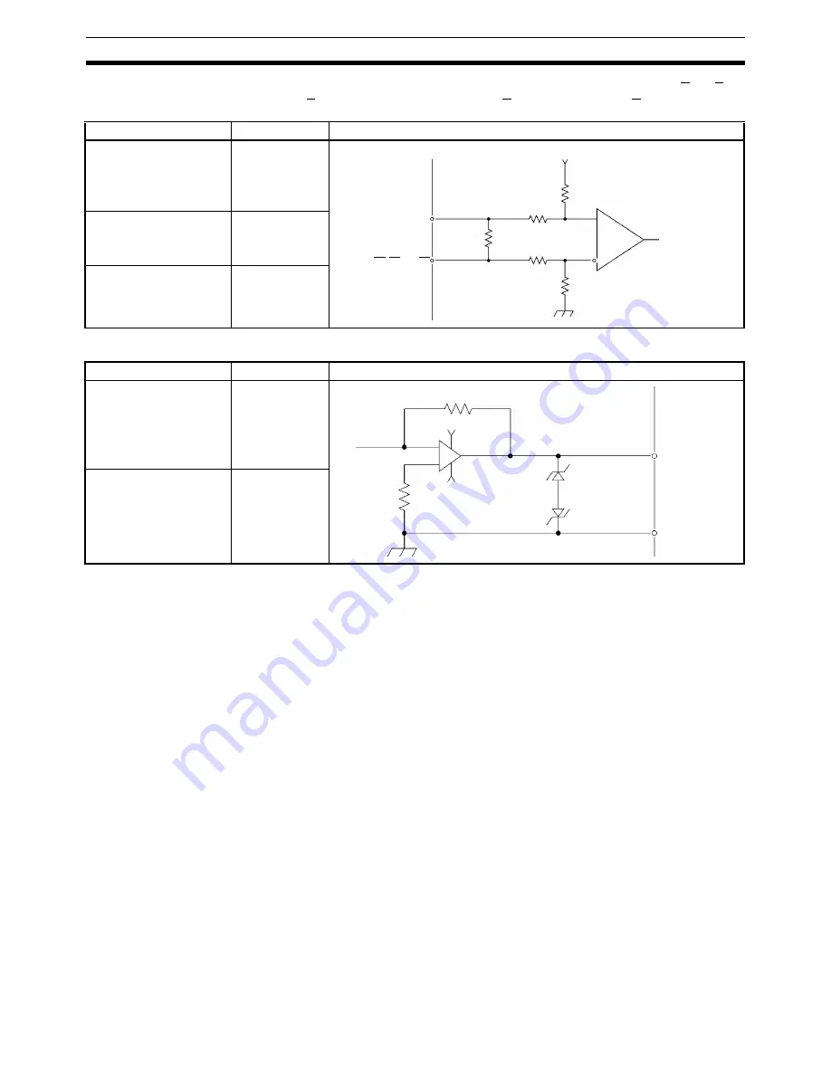
The circuit in the table below is used to interface phase inputs A, A, B, B, Z,
and Z (for X to U) and MPG-A, MPG-A, MPG-B, and MPG-B.
The circuit in the table below is used to interface outputs OUT (X to U).
2-3-8
Wiring Precautions
Heed the following precautions when wiring the MC Unit to the servo drivers
and motors.
Electronically controlled equipment may malfunction because of noise gener-
ated by power supply lines or external loads. Such malfunctions are difficult to
reproduce; hence, determining the cause often requires a great deal of time.
The following tips should aid in avoiding noise malfunction and improving sys-
tem reliability.
Use electrical wires or cables of 0.2 mm
2
or as specified in the instruction
manual for the servo driver.
Use larger size cables for the FG lines of the PLC or the driver and ground
them over the shortest possible distance.
Separate power cables (AC power supply lines and motor power supply lines)
from control cables (pulse output lines and external input signal lines). Do not
group the two types of cable together or place them in the same conduit. Use
shielded cables for control lines.
Item
Specification
Circuit Configuration
Signal level
EIA RS-422-A
Standards
Input impedance
220
Ω
Response frequency
500 kp/s max.
Phase A, B, or Z
Line receiver
Phase A, B, or Z
1/2W
220
Ω
5 V
Item
Specification
Circuit Configuration
Output voltage
0 to
±
10 V
Load impedance
10 k
Ω
min.
+15 V
−
15 V
X to U OUT
X to U AGND
Содержание CS1W-MC221 -
Страница 1: ...Motion Control Units Cat No W359 E1 04 CS1W MC221 V1 421 V1 OPERATION MANUAL ...
Страница 2: ...CS1W MC221 V1 421 V1 Motion Control Units Operation Manual Revised February 2008 ...
Страница 3: ...iv ...
Страница 5: ...vi ...
Страница 11: ...xii ...
Страница 15: ...xvi ...
Страница 19: ...xx ...
Страница 27: ...xxviii Conformance to EC Directives 6 ...
Страница 133: ...106 Installation Section 2 2 2 2 4 Dimensions CS1W MC421 CS1W MC221 ...
Страница 173: ...146 Connecting Peripheral Devices Section 2 7 ...
Страница 227: ...200 Command Area Section 3 6 ...
Страница 351: ...324 Interface Specifics Section 5 4 ...
Страница 513: ...486 Absolute Encoder Interface Specifications Section 9 7 ...
Страница 575: ...548 Error Log Section 12 6 ...
Страница 589: ...562 Performance Appendix A ...
Страница 655: ...628 Control Bit Flag Timing Charts Appendix E ...
Страница 683: ...656 Origin Search Patterns Appendix F ...
Страница 685: ...658 Encoder Divider Rate and Rotation Speed for OMRON Servo Drivers Appendix G ...


