556
Performance
Appendix A
4.
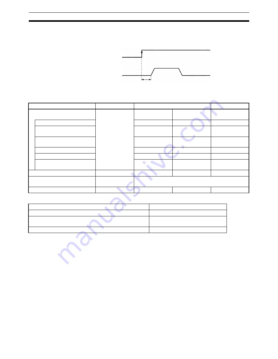
The option response time is the time from when a general-purpose input turns ON until an analog
voltage is output, e.g., as in N010 G01 X100 F1000 #16, where “#16” is option input 16 and corre-
sponds to general-purpose input 1.
CS1W-MC421
Other Response Times
1.
The Cycle Start Bit ON Response Time is the time from when the Cycle Start Bit turns ON until an
analog voltage is output for the next block, e.g., block N010 in the following code.
N000 Pxxx xxxx
N010 <
G code for above
>
2.
The response times for an X-axis operation are for when only 1 axis is moved without being affected
by the task configuration, e.g., as in G00 X100 or G01 X100 F100.
3.
The response times for an X, Y-axis operation are for when all axes are moved, e.g., as in G00 X100
Y100 or G01 X100 Y100 Z100 U100 F100.
4.
The response time for an X, Y circular interpolation.
5.
The response time for an X, Y traverse operation.
Voltage output
General-purpose input 1
Response time
Command
Conditions
1 task, 2 axes
2 tasks, 2 axes
Cycle Start Bit ON Response Time
(See note 1.)
All axes stopped.
X-axis operation
(See note 2.)
X, Y-axis operation
(See note 3.)
X-axis operation
G00: PTP CONTROL
7.0 to 11.0 ms
8.1 to 11.5 ms
9.3 to 12.3 ms
G01: LINEAR
INTERPOLATION
7.6 to 10.4 ms
8.8 to 11.7 ms
6.6 to 11.1 ms
G02/G03: CIRCULAR
INTERPOLATION
---
8.5 to 11.2 ms
(See note 4.)
---
G30: SPEED CONTROL
7.0 to 11.0 ms
8.1 to 11.5 ms
9.3 to 12.3 ms
G31: INTERRUPT FEED
7.1 to 9.9 ms
8.1 to 11.2 ms
6.3 to 9.5 ms
G32: TRAVERSE
---
8.5 to 11.2 ms
(See note 5.)
---
When changing override
All axes stopped.
3.6 to 11.1 ms
3.6 to 11.5 ms
4.6 to 12.3 ms
Option response time
(See note 6.)
All axes stopped.
2.5 to 4.5 ms
Jogging
All axes stopped.
5.0 to 11.1 ms
4.8 to 11.0 ms
6.8 to 11.4 ms
Command
Response time
Origin search and origin return
Same as for jogging
Forced block end, pause, deceleration stop, error counter reset,
M code reset for M500 to M999
Same as for changing override
M code reset for M0 to M499
Same as for Cycle Start Bit ON
Содержание CS1W-MC221 -
Страница 1: ...Motion Control Units Cat No W359 E1 04 CS1W MC221 V1 421 V1 OPERATION MANUAL ...
Страница 2: ...CS1W MC221 V1 421 V1 Motion Control Units Operation Manual Revised February 2008 ...
Страница 3: ...iv ...
Страница 5: ...vi ...
Страница 11: ...xii ...
Страница 15: ...xvi ...
Страница 19: ...xx ...
Страница 27: ...xxviii Conformance to EC Directives 6 ...
Страница 133: ...106 Installation Section 2 2 2 2 4 Dimensions CS1W MC421 CS1W MC221 ...
Страница 173: ...146 Connecting Peripheral Devices Section 2 7 ...
Страница 227: ...200 Command Area Section 3 6 ...
Страница 351: ...324 Interface Specifics Section 5 4 ...
Страница 513: ...486 Absolute Encoder Interface Specifications Section 9 7 ...
Страница 575: ...548 Error Log Section 12 6 ...
Страница 589: ...562 Performance Appendix A ...
Страница 655: ...628 Control Bit Flag Timing Charts Appendix E ...
Страница 683: ...656 Origin Search Patterns Appendix F ...
Страница 685: ...658 Encoder Divider Rate and Rotation Speed for OMRON Servo Drivers Appendix G ...


