


152
System Parameters
Section 3-3
3-3-2
Description of System Parameters
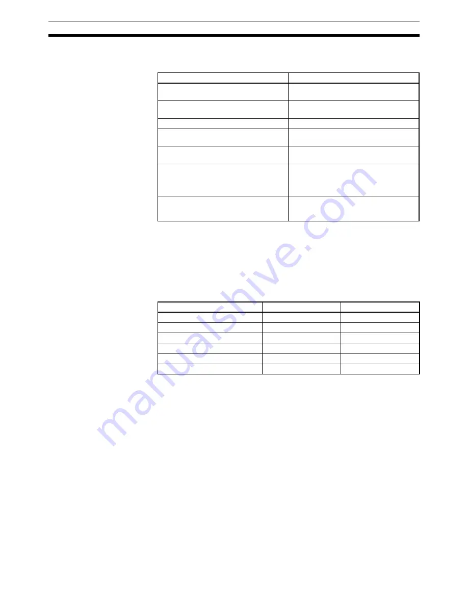
Unit Parameters
The following unit parameters can be set.
Note
1.
Parenthesis indicate CS1W-MC221 settings.
2.
Be sure to set these three task configuration-related settings (axis config-
uration, number of tasks, and task axis declaration) as initial settings.
The following table shows the default settings. Be sure to change the unit
parameters (axis configuration, number of tasks, and task axis declaration)
if you use a task configuration other than that in the table.
Default Task Configuration
The MC programs are managed by the number of tasks, and new MC pro-
grams must be created for a new task configuration if the above parameters
are changed after the MC programs have been created. Refer to
3-2 Deter-
mining the Task Configuration
for the procedure to change the task configura-
tion.
Memory Management
Parameter
The memory management parameter is used to set position data for each
task. An MC program can use a total of 2,000 position data addresses (A0000
to A1999). This parameter is used to prevent data from being incorrectly used
when two or more tasks are involved.
Parameter name
Function
Axis configuration (See note 2.)
Sets the number of axes to use in the MC
Unit: 1 to 4 (2) axes
Number of tasks (See note 2.)
Sets the number of tasks to use in the
MC Unit: 1 to 4 (2) tasks
Task axis declaration (See note 2.)
Sets the axes used for each task
Output port setting
Sets whether a general output or brake
signal output is output from the port.
MPG/sync encoder setting
Sets whether to use an MPG or a sync
encoder.
Pass Mode
Selects the time for switching to the next
operation in pass operation and sets
whether to use constant acceleration feed
rate when operating just one axis.
Teaching Box language/autoload timeout
Selects the Teaching Box message
language and sets the automatic loading
time up time.
Parameter
CS1W-MC421
CS1W-MC221
Axis configuration
4 axes
2 axes
Number of tasks
1 task
1 task
Task axis declaration for task 1
X, Y, Z and U axes
X and Y axes
Task axis declaration for task 2
Not used.
Not used.
Task axis declaration for task 3
Not used.
Not used.
Task axis declaration for task 4
Not used.
Not used.
Содержание CS1W-MC221 -
Страница 1: ...Motion Control Units Cat No W359 E1 04 CS1W MC221 V1 421 V1 OPERATION MANUAL ...
Страница 2: ...CS1W MC221 V1 421 V1 Motion Control Units Operation Manual Revised February 2008 ...
Страница 3: ...iv ...
Страница 5: ...vi ...
Страница 11: ...xii ...
Страница 15: ...xvi ...
Страница 19: ...xx ...
Страница 27: ...xxviii Conformance to EC Directives 6 ...
Страница 133: ...106 Installation Section 2 2 2 2 4 Dimensions CS1W MC421 CS1W MC221 ...
Страница 173: ...146 Connecting Peripheral Devices Section 2 7 ...
Страница 227: ...200 Command Area Section 3 6 ...
Страница 351: ...324 Interface Specifics Section 5 4 ...
Страница 513: ...486 Absolute Encoder Interface Specifications Section 9 7 ...
Страница 575: ...548 Error Log Section 12 6 ...
Страница 589: ...562 Performance Appendix A ...
Страница 655: ...628 Control Bit Flag Timing Charts Appendix E ...
Страница 683: ...656 Origin Search Patterns Appendix F ...
Страница 685: ...658 Encoder Divider Rate and Rotation Speed for OMRON Servo Drivers Appendix G ...


