UniPOS
Wireless Fire Alarm Control Panel VIT 01
Instruction manual
Page 1
Revision 10/02.17
Pages 51
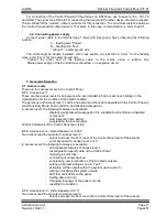
WIRELESS FIRE ALARM CONTROL PANEL
VIT01
INSTRUCTION MANUAL
Страница 1: ...UniPOS Wireless Fire Alarm Control Panel VIT 01 Instruction manual Page 1 Revision 10 02 17 Pages 51 WIRELESS FIRE ALARM CONTROL PANEL VIT01 INSTRUCTION MANUAL Revision 10 02 17...
Страница 2: ...scription Indication Using the keypad Fire condition Description Indication Using the keypad Fault condition Description Indication Using the keypad Disabled component Description Indication Using the...
Страница 3: ...n 10 02 17 Pages 51 17 1 17 2 17 3 17 4 17 5 18 Checking for other devices working on the same band Preliminary radio test Routers and parents Several steps in building configuration Possible reasons...
Страница 4: ...r connection with personal computer different ways possibility of installation designs within the range of the control panel s resources 1 Terminology Addressable point Detector or manual call point t...
Страница 5: ...ted directly to the Control Panel 20 Maximum number of fire detectors connected to router 14 2 3 Controllable outputs 2 pcs Type potential relay Electrical features 24 5 V DC 1 A 2 4 Relay output for...
Страница 6: ...Defining of the structure of the radio network It is necessary before installation to define the structure of the radio network On fig 1 1 1 2 and 1 3 are shown different types of connection In the f...
Страница 7: ...nnection is scanning for a Router or for a Control Panel with the best quality connection Ones detectors find its Control Panel or Router communication in the future work of the detector will be imple...
Страница 8: ...o R3 R2 R1 and the Control Panel 4 2 Installation of the Control Panel unpack the Control Panel mount the dowels for fixing the Control Panel onto a specific place fix the Control Panel to the dowels...
Страница 9: ...o peripheral devices RS232 485 Terminals for connection of two wire line of interface RS485 or three wire line for RS232 Switching between interfaces is done by changing position of a jumper on the bo...
Страница 10: ...The output is not monitored for short curcuit or interruption The relay contacts do not commutate 220V 4 3 3 Monitored outputs Out1 and Out2 Outputs are connecten on two wire line for connection with...
Страница 11: ...on the signalizations for fire condition or and fault condition The personnel with Access level 1 shall be trained and authorized to operate with the Control Panel in conditions Duty Mode Fault condi...
Страница 12: ...can not be combined with another condition Entering Set Up condition exits all the other conditions The Control Panel conditions and their corresponding indications are described in Table 1 Table 1 Co...
Страница 13: ...rm data Next position Button Down Set Up Fire condition Fault condition Test and Disabled component Levels 2 and 3 Selects next basic screen Moves the cursor through menus Selects next parameter Butto...
Страница 14: ...screen select next main screen o In the screen with menu move the cursor up and over the elements of the menu o In the screen for changing the parameter increase and decrease the current value of the...
Страница 15: ...ith red light the indicator of the relevant zone If the outputs for fire condition are suppressed by button Outputs the LED indicator of the button is illuminated in continuous red light If the sound...
Страница 16: ...reas where the fire condition occurs Button Access Level Action Additional information Button Alarm All Pressing the button switched off the local sounder activates the local sounder if the Control Pa...
Страница 17: ...scription The Fire Control Panel enters Fault Condition upon detecting fault in one of the modules or and in one of the devices registered within the system A list of possible faults is given in Appen...
Страница 18: ...Control Panel has entered Fire or Fault condition and the local sounder was switched off by previous pressing of this button The action of the button is reversible i e by single pressing changes the c...
Страница 19: ...ing the keypad Button Access Level Action Additional information Button Menu All Pressing the button enters condition information and control All the disabled components can be reviewed from menu Disa...
Страница 20: ...he system components This condition can operate in combination with the following modes of the Control Duty Mode Fire Condition Disabled component mode Test mode Fault condition mode Set Up mode 11 2...
Страница 21: ...he dispay to the previous main screen o In the screen for changing the parameter records the changes of the parameters if changes were made and returns the display to the previous main screen 11 4 Usi...
Страница 22: ...he status of all outputs The conditions of output 1 output 2 are shown consecutively and if there are routers registered in the network the conditions of their outputs are also shown button returns th...
Страница 23: ...ccurance Records are devided into three main groups Records for fire condition Records for fault condition All records In Appendix 3 is given a list of all possible records contained in the archive Ac...
Страница 24: ...eans of button proceed to the next digit Enter the other digits by the same procedure The password validity is checked after entering the last digit Upon entering a correct password the Control Panel...
Страница 25: ...h italic and bold type are accessible only with password in access level 3 All others are accessable in access level 2 Panel chapter 12 4 1 Test chapter 12 4 1 1 Outputs chapter 12 4 1 1 1 Indication...
Страница 26: ...address and others 12 4 1 1 Submenu Test 12 4 1 1 1 Outputs shows the status of the outputs of the Control Panel Buttons and show the condition of the monitor outputs the outputs of the routers and a...
Страница 27: ...s supply E ground H Monitor output 2 is shorted L Monitor output 2 interrupted h Monitor output 1 shorted l Monitor output 1 interrupted D Fault in the output supply 28V A Fault 220V supply 12 4 1 1 2...
Страница 28: ...tton to proceed to the next parameter 12 4 1 3 2 Ground check Enables or disables the monitoring of fault ground Buttons and change the parameter alternatively Possible values Yes No Press button to m...
Страница 29: ...et Up mode was entered password for level 3 The cursor is positioned on the first digit Buttons and are changing the parameter Press button to move to the next digit Holding down the button on a rando...
Страница 30: ...he second line displays the number of the outputs in Fire 1 and Fire 2 The last line shows the number of the fire detectors belonging to that zone Buttons and are displaying information about the othe...
Страница 31: ...sible sets of characters are different for Bulgarian _ 9876543210 for English and Italian _ABCDEFGHIJKLMNOPQRSTUVWXYZ 9876543210 12 4 2 2 2 Parameter Inspection time The inspection time is additionall...
Страница 32: ...hin the system are shown consecutively as parameters Monitored output 1 Monitored output 2 and all outputs of the registered routers controllers Each of them must be set with value Yes or No Thus ther...
Страница 33: ...both types is identical On the first line are described the type of registration and the idenetical code of the radio network On the second channel andthe identical code of the last registered device...
Страница 34: ...e registration or to enter submenu Channels button to activate the parameter or the submenu and to return to the main screen button to exit Upon selecting submenu Channels on the display are indicated...
Страница 35: ...temperature measurement B low battery failed back up battery supply to the router P open detector failed user supply voltage to the peripheral devices to router D normal operation of the measuring sys...
Страница 36: ...r is able to enter Fire Condition or Fault condition only from this mode o Service mode for diagnostics and settings of the devices Unlike the others in this mode the devices maintain a continuous rad...
Страница 37: ...ection of new devices to the router This function does not affect of the operation of the already connected to the router devices o Switching off the router from the mains leads to their disconnection...
Страница 38: ...pt mandatory output for activation relay for Fire If the described device is a router it shall be described by the procedure above as only the name requires description the routers can be selected as...
Страница 39: ...ve function for the operator of the system and can not be changed Parameter Parent This parameter indicates whether the device has saved router or control panel as a device that communicates through t...
Страница 40: ...mbined fire detectors Measurement period in Duty Mode Measurement period in Service Mode Level Low battery Thermal sensor switched ON for combined fire detectors Optical smoke sensor switched ON for c...
Страница 41: ...eter Measurement period in Service Mode The parameter sets the interval in seconds between the two consecutive measurements of the device in Service Mode Parameter Low Battery Level The parameter sets...
Страница 42: ...cords for devices will be deleted and all parameters from the control panel will be set back to default 13 Labour protection requirements The installation and maintenance staff must be well familiar w...
Страница 43: ...eration stated at the Instruction Manual herein have been observed 17 Recommendations before final installing of wireless fire alarm system on site 17 1 Checking for other devices working on the same...
Страница 44: ...rom the panel If this status continue more than 15 seconds the radio attenuation between detector and control panel or a router is too high and proper communication can not be established 17 3 Routers...
Страница 45: ...d its address can be found in P parameter 17 4 Several steps building your ownconfiguration Set default parameters to your panel select Setup Registration Auto and hold Reset button for more than 10 s...
Страница 46: ...tons you must find and display on panel s screen the router s C1 parameters In this way you will activate the registration mode of the router C1 If letter D is presented in the status of C1 means that...
Страница 47: ...ed in the construction of the building is possible to have a higher ability to absorbing radio waves large distance between components Average range ensures proper communication between detector and r...
Страница 48: ...cator Fault in monitored output 6 Indicator Disabled component 7 Indicator Test 8 Button Menu 9 Button Down 10 Button Up 11 Button Cancel 12 Zone indicators for Fire and Fault 13 Indicator Power suppl...
Страница 49: ...3 Panel 11 4 1 4 Fires Faults All Parameters 12 4 1 3 Panel 12 4 1 Clock 12 4 1 2 Test 12 4 1 1 Language Ground check Net Address Level 2 Pass Del Arch 12 4 1 4 Outputs Ph1 12 4 2 3 Zones 12 4 2 Param...
Страница 50: ...l S e n s itiv ity O n O ff o p tic a l d e te c to r S w O ff C h a n g e m o d e A u to r e g S w O n O u t In p u t O n A u to r e g D is D is a b le O n O ff th e r m a l d e te c to r fo r V IT...
Страница 51: ...e radio network Control Panel Default parameters Inform Restored default setting of the Control Panel Control Panel Start Evacuation Inform Switching on all the outputs in Duty Mode Control Panel Stop...