


UniPOS
Wireless Fire Alarm Control Panel VIT 01
Instruction manual
Page 17
Revision 10/02.17
Pages 51
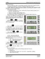
Button
(„Inspection”)
All
Adds Inspection time in the Control
Panel is in
„Fire 1”.
Time is set for each zone.
If this button is pressed when
the Control Panel is in
„Fire 1”,
that increases the time period
between phase 1 and phase 2 of
the occurred fire condition with
set inspection time until the
Control Panel enters
„Fire 2”.
Button
(“Reset”)
2
nd
or
higher
Pressing the button forces the
control panel to exit from Fire
condition
– clears all fires in all
zones
Operating with the button
requires access level 2 or higher.
Button
(“Menu”)
All
Pressing the button enters
condition Information and control.
Check the condition of the
fire detectors and the current fault
conditions.
Buttons
(„Up”
and
„Down”)
и
All
If the fire conditions are more
than one, information about each of
them is displayed by means of the
buttons.
Button
(“Exit”)
All
Pressing the button leads to exit
from the condition Information and
control. The main screen in the
current Fire condition is visualized.
8. Fault condition
8.1. Description
The Fire Control Panel enters
„Fault Condition” upon detecting fault in one of the modules or/and
in one of the devices, registered within the system;
A list of possible faults is given in Appendix 2.
8.2. Indication
8.2.1.
LED and sound indication
For all fault conditions, indicator
(“Fault”) is on with continuous yellow light. Depending on
the type of the fault condition, the following indicators are also illuminated:
In system fault - indicator
(“System fault”) with continuous yellow light;
fault in a controllable output - indicator
(“Fault short-circuit or an interrupted controllable
output
”) with flashing yellow light;
in fault of the mains or back up batteries supply - indicator
(“Fault Power supply”)is
illuminated with continuous yellow light;
in fault in any of the fire detectors, the indicator of the zone, to which it belongs
is illuminated in flashing yellow light.
The local sounder is activated and produces discontinuous signal. In case the sound signalization is
suppressed by button
(“Alarm”), the LED indicator of the button is illuminated in continuous red
light.
8.2.2.Text indication
The screens of fatal faults suppress all other messages. In the occurance of more then one non-
fatal faults, they are indicated by their time of appearing. Last fault is indicated on the display.


