20
Specifications
Section 1-5
6.
The maximum position command values, software limit values, and zone
values are as shown in the following table for each minimum setting unit.
The actual maximum ranges that can be set may be smaller than those
shown above depending on the pulse rate. The maximum set value must
satisfy the following two conditions:
• |Set value (C)|
≤
1073741823 x P
• |Set value (C)|
≤
39999999 (C)
P:
Pulse rate (Pulse/pulse, mm/pulse, degrees/pulse, and inch/pulse)
C:
Minimum setting unit (1, 0.1, 0.01, 0.001, 0.0001)
Example:
If the minimum setting unit is 0.01 and pulse rate is 0.0001, the
maximum set value can be calculated as follows:
1073741823 x 0.0001=10734.1823 < 399999.99
Therefore, the maximum range is –10734.18 to 10734.18 (because the
minimum setting unit is 0.01).
Also, the maximum present position shown by CX-Motion or the Teaching
Box will be within the ranges indicated in the table above.
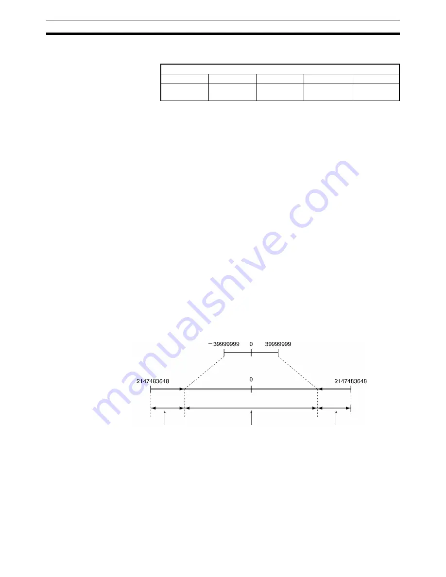
Demand Positions and
Present Positions
Data is stored internally in the MC Unit for the demand positions, software lim-
its, present positions, zones, reference origin offsets, and workpiece origin off-
sets as 32-bit signed data in pulse units. The Teaching Box, CX-Motion, and
CPU Unit, however, handle data in millimeters within the ranges described in
note 2 for the above table. Depending on the pulse rate setting, the axes may
move or stop in positions that cannot be handled by these devices. If a posi-
tion is beyond the range that can be handled by these devices, it will be indi-
cated as the maximum (399,999,999) or minimum (–399,999,999) value until
the position returns within the range that can be indicated.
Note
1.
The present position data held inside the MC Unit (32-bit signed data) can
be directly read by the CPU Unit using the IORD instruction. Use address-
es 17BA hex, 17BB hex, 17BC hex, and 17BD hex.
2.
The present position monitoring function of the CX-Motion can be used to
display the reference coordinate system present value in pulses between
–268,435,455 and 268,435,455 (28-bit data).
Minimum setting unit
1
0.1
0.01
0.001
0.0001
–39999999 to
+39999999
–3999999.9 to
+3999999.9
–399999.99 to
+399999.99
–39999.999 to
+39999.999
–3999.9999 to
+3999.9999
Range of position data (mm) that can be
transferred between the MC Unit and other
devices (Teaching Box, CX-Motion, and CPU
Unit)
Position data (pulses)
handled inside the MC Unit
The position will
be indicated as
−
39,999,999 in
this range.
The position will be transferred
and updated in this range.
The position will
be indicated as
39,999,999 in this
range.
Pulse rate
conversion
Pulse rate
conversion
Содержание CS1W-MC221 -
Страница 1: ...Motion Control Units Cat No W359 E1 04 CS1W MC221 V1 421 V1 OPERATION MANUAL ...
Страница 2: ...CS1W MC221 V1 421 V1 Motion Control Units Operation Manual Revised February 2008 ...
Страница 3: ...iv ...
Страница 5: ...vi ...
Страница 11: ...xii ...
Страница 15: ...xvi ...
Страница 19: ...xx ...
Страница 27: ...xxviii Conformance to EC Directives 6 ...
Страница 133: ...106 Installation Section 2 2 2 2 4 Dimensions CS1W MC421 CS1W MC221 ...
Страница 173: ...146 Connecting Peripheral Devices Section 2 7 ...
Страница 227: ...200 Command Area Section 3 6 ...
Страница 351: ...324 Interface Specifics Section 5 4 ...
Страница 513: ...486 Absolute Encoder Interface Specifications Section 9 7 ...
Страница 575: ...548 Error Log Section 12 6 ...
Страница 589: ...562 Performance Appendix A ...
Страница 655: ...628 Control Bit Flag Timing Charts Appendix E ...
Страница 683: ...656 Origin Search Patterns Appendix F ...
Страница 685: ...658 Encoder Divider Rate and Rotation Speed for OMRON Servo Drivers Appendix G ...


