


187
Position Data
Section 3-4
If the position loop gain is too low, motor response will deteriorate because
there will be too many accumulated pulses. If the position loop gain is too
high, oscillation and noise might occur. In general, the setting should be 50 to
70 (1/s) for NC machine tools, 30 to 50 (1/s) for multi-purpose machines and
assembly machines, and 10 to 30 (1/s) for industrial robots.
The setting range is 1 to 250 and the default setting is 40 (1/s).
Position Loop FF Gain
Sets the position loop FF (feed-forward) gain. The setting range is 0 to 100
(%), and the default setting is 0 (%).
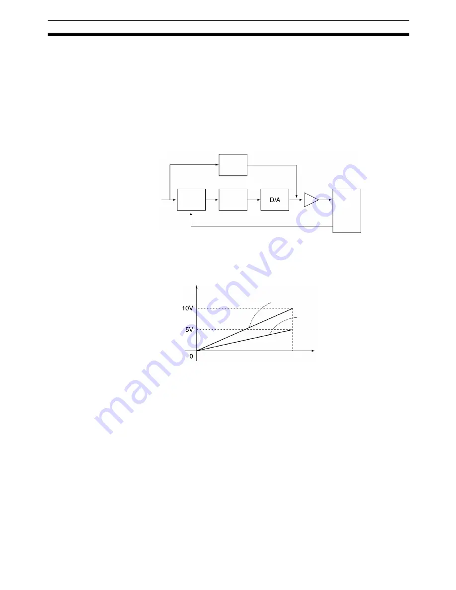
The position loop FF gain process the speed reference pulses and reduces
the positioning time by adding directly to the command voltage.
The following diagram shows the relationship between the position loop FF
gain and the speed reference pulses.
Backlash Correction
This parameter sets backlash correction for the mechanical system. The set-
ting range is 0 to 10,000 pulses and the default setting is 0 pulses. Refer to
6-15 Backlash Correction
for more details.
Brake ON/OFF Time
This parameter sets the brake ON/OFF time. The setting range is 0 to 10,000
ms and the default setting is 0 ms. Refer to the brake manual and adjust the
proper time for the system.
Refer to
Servo Lock
(page 241) and
Servo Unlock
(page 241) in
5-3 PLC
Interface Area
and
6-14 Servo Lock and Unlock
.
3-4
Position Data
There are 2,000 positions that can be used. An axis is positioned by specify-
ing the position directly in a G-language program or it is positioned by specify-
ing a position in the position data (specifying indirectly). Position data is
transferred to and from an MC Unit by writing a specific transfer command in
the command area (addresses 6102/6103) using CX-Motion, IOWR/IORD
instructions or IOWR instructions.
Speed reference pulses
Error
counter
Position
loop gain
Servo
driver
Position
loop FF
gain
Amplifier
Feedback pulses
Command
voltage
Speed reference pulses
Position loop FF gain 100%
Command
voltage
Position loop FF gain 50%
Max. speed reference value
(Max. motor speed)
Содержание CS1W-MC221 -
Страница 1: ...Motion Control Units Cat No W359 E1 04 CS1W MC221 V1 421 V1 OPERATION MANUAL ...
Страница 2: ...CS1W MC221 V1 421 V1 Motion Control Units Operation Manual Revised February 2008 ...
Страница 3: ...iv ...
Страница 5: ...vi ...
Страница 11: ...xii ...
Страница 15: ...xvi ...
Страница 19: ...xx ...
Страница 27: ...xxviii Conformance to EC Directives 6 ...
Страница 133: ...106 Installation Section 2 2 2 2 4 Dimensions CS1W MC421 CS1W MC221 ...
Страница 173: ...146 Connecting Peripheral Devices Section 2 7 ...
Страница 227: ...200 Command Area Section 3 6 ...
Страница 351: ...324 Interface Specifics Section 5 4 ...
Страница 513: ...486 Absolute Encoder Interface Specifications Section 9 7 ...
Страница 575: ...548 Error Log Section 12 6 ...
Страница 589: ...562 Performance Appendix A ...
Страница 655: ...628 Control Bit Flag Timing Charts Appendix E ...
Страница 683: ...656 Origin Search Patterns Appendix F ...
Страница 685: ...658 Encoder Divider Rate and Rotation Speed for OMRON Servo Drivers Appendix G ...


