ISD94100 Series Technical Reference Manual
Sep 9, 2019
Page
817
of 928
Rev1.09
IS
D
9
410
0
S
ER
IE
S
T
E
C
HN
ICA
L
RE
F
E
RE
NCE
M
AN
U
AL
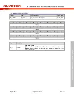
[15]
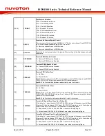
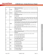
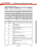
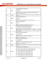
MCLKEN
Master Clock Enable Control
If MCLKEN is set to 1, I
2
S controller will generate master clock on I2S_MCLK pin for external
audio devices.
0 = Master clock Disabled.
1 = Master clock Enabled.
[14:9]
Reserved
Reserved. Any values read should be ignored. When writing to this field always write with
reset value.
[8]
SLAVE
Slave Mode Enable Control
0 = Master mode.
1 = Slave mode.
Note:
I
2
S can operate as master or slave. For Master mode, I2S_BCLK and I2S_LRCLK
pins are output mode and send out bit clock to Audio CODEC chip. In Slave mode,
I2S_BCLK and I2S_LRCLK pins are input mode and I2S_BCLK and I2S_LRCLK signals
are received from outer Audio CODEC chip.
[7]
ORDER
Stereo Data Order in FIFO
In 8-bit/16-bit data width, this bit is used to select whether the even or odd channel data is
stored in higher byte. In 24-bit data width, this is used to select the left/right alignment
method of audio data which is stored in data memory consisted of 32-bit FIFO entries.
0 = Even channel data at high byte in 8-bit/16-bit data width.
LSB of 24-bit audio data in each channel is aligned to right side in 32-bit FIFO entries.
1 = Even channel data at low byte.
MSB of 24-bit audio data in each channel is aligned to left side in 32-bit FIFO entries.
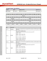
[6]
MONO
Monaural Data Control
0 = Data is stereo format.
1 = Data is monaural format.
Note:
when chip records data, RXLCH (I2S_CTL0[23]) indicates which channel data will be
saved if monaural format is selected.
[5:4]
DATWIDTH
Data Width
This bit field is used to define the bit-width of data word in each audio channel
00 = The bit-width of data word is 8-bit.
01 = The bit-width of data word is 16-bit.
10 = The bit-width of data word is 24-bit.
11 = The bit-width of data word is 32-bit.
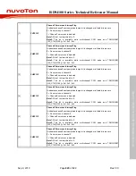
[3]
MUTE
Transmit Mute Enable Control
0 = Transmit data is shifted from buffer.
1 = Send zero on transmit channel.
[2]
RXEN
Receive Enable Control
0 = Data receiving Disabled.
1 = Data receiving Enabled.
[1]
TXEN
Transmit Enable Control
0 = Data transmission Disabled.
1 = Data transmission Enabled.
[0]
I2SEN
I
2
S Controller Enable Control
0 = I
2
S controller Disabled.
1 = I
2
S controller Enabled.
Содержание ISD94100 Series
Страница 528: ...ISD94100 Series Technical Reference Manual Sep 9 2019 Page 528 of 928 Rev1 09 ISD94100 SERIES TECHNICAL REFERENCE MANUAL...
Страница 626: ...ISD94100 Series Technical Reference Manual Sep 9 2019 Page 626 of 928 Rev1 09 ISD94100 SERIES TECHNICAL REFERENCE MANUAL...
Страница 702: ...ISD94100 Series Technical Reference Manual Sep 9 2019 Page 702 of 928 Rev1 09 ISD94100 SERIES TECHNICAL REFERENCE MANUAL...
Страница 875: ...ISD94100 Series Technical Reference Manual Sep 9 2019 Page 875 of 928 Rev1 09 ISD94100 SERIES TECHNICAL REFERENCE MANUAL...


