ISD94100 Series Technical Reference Manual
Sep 9, 2019
Page
866
of 928
Rev1.09
IS
D
9
410
0
S
ER
IE
S
T
E
C
HN
ICA
L
RE
F
E
RE
NCE
M
AN
U
AL
6.19 Digital Microphone Inputs (DMIC)
6.19.1 Overview
Using the dual channel digital PDM (Pulse Density Modulation) microphone interface (DMIC_CLK0,
DMIC_DAT0, DMIC_CLK1 and DMIC_DAT1 pins) that are handled four digital PDM microphone
inputs. Both DMIC_DAT0 and DMIC_DAT1 inputs are able to handle two digital microphones by
selecting them alternately for each half of the clock cycle.
6.19.2 Features
The digital microphone interface use two wires (DMIC_DATn and DMIC_CLKn) to receive
information from digital microphones. The main features of DMIC includes:
Provides one 32-level FIFO data buffers for receiving.
Generates interrupt requests when buffer levels cross a programmable boundary.
Supports PDMA transfer.
Supports up to four channel digital microphones.
Both digital PDM microphone inputs can be used simultaneously.
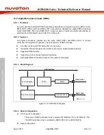
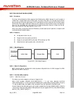
6.19.3 Block Diagram
Control Register
APB Interface
DMIC_CLKn
DMIC_DATn
PDMA
Buffer
Interface Control
Bus Clock Control
Note:
n = 0 or 1
Figure 6.19-1 DMIC Block Diagram
6.19.4 Basic Configuration
Clock source configuration
–
The source of DMIC peripheral clock is selected by DMICSEL (CLK_CLKSEL2[11:10]).
–
The DMIC peripheral clock is enabled by DMICCKEN (CLK_APBCLK0[15]).
Reset configuration
Содержание ISD94100 Series
Страница 528: ...ISD94100 Series Technical Reference Manual Sep 9 2019 Page 528 of 928 Rev1 09 ISD94100 SERIES TECHNICAL REFERENCE MANUAL...
Страница 626: ...ISD94100 Series Technical Reference Manual Sep 9 2019 Page 626 of 928 Rev1 09 ISD94100 SERIES TECHNICAL REFERENCE MANUAL...
Страница 702: ...ISD94100 Series Technical Reference Manual Sep 9 2019 Page 702 of 928 Rev1 09 ISD94100 SERIES TECHNICAL REFERENCE MANUAL...
Страница 875: ...ISD94100 Series Technical Reference Manual Sep 9 2019 Page 875 of 928 Rev1 09 ISD94100 SERIES TECHNICAL REFERENCE MANUAL...

