ISD94100 Series Technical Reference Manual
Sep 9, 2019
Page
826
of 928
Rev1.09
IS
D
9
410
0
S
ER
IE
S
T
E
C
HN
ICA
L
RE
F
E
RE
NCE
M
AN
U
AL
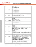
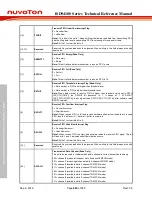
[16]
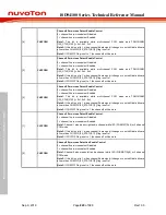
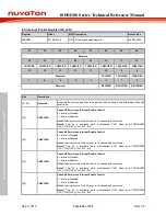
TXUDIF
Transmit FIFO Underflow Interrupt Flag
0 = No underflow.
1 = Underflow.
Note1:
This bit will be set to 1 when shift logic hardware read data from transmitting FIFO
and the filling data level in transmitting FIFO is not enough for one audio frame.
Note2:
Write 1 to clear this bit to 0.
[15:13]
Reserved
Reserved. Any values read should be ignored. When writing to this field always write with
reset value.
[12]
RXEMPTY
Receive FIFO Empty (Read Only)
0 = Not empty.
1 = Empty.
Note:
This bit reflects data words number in receive FIFO is zero
[11]
RXFULL
Receive FIFO Full (Read Only)
0 = Not full.
1 = Full.
Note:
This bit reflects data words number in receive FIFO is 16.
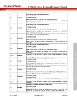
[10]
RXTHIF
Receive FIFO Threshold Interrupt Flag (Read Only)
0 = Data word(s) in FIFO is not higher than threshold level.
1 = Data word(s) in FIFO is higher than threshold level.
Note:
When data word(s) in receive FIFO is higher than threshold value set in RXTH
(I2S_CTL1[19:16]) the RXTHIF bit becomes to 1. It keeps at 1 till RXCNT
(I2S_STATUS1[20:16]) is not higher than RXTH (I2S_CTL1[19:16]) after software read
RXFIFO register.
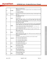
[9]
RXOVIF
Receive FIFO Overflow Interrupt Flag
0 = No overflow occur.
1 = Overflow occur.
Note1:
When receive FIFO is full and receive hardware attempt to write data into receive
FIFO then this bit is set to 1, data in 1
st
buffer is overwrote.
Note2:
Write 1 to clear this bit to 0.
[8]
RXUDIF
Receive FIFO Underflow Interrupt Flag
0 = No underflow occur.
1 = Underflow occur.
Note1:
When receive FIFO is empty, and software reads the receive FIFO again. This bit
will be set to 1, and it indicates underflow situation occurs.
Note2:
Write 1 to clear this bit to zero
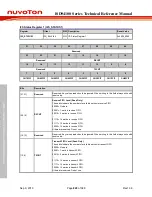
[7:6]
Reserved
Reserved. Any values read should be ignored. When writing to this field always write with
reset value.
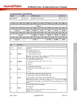
[5:3]
DATACH
Transmission Data Channel (Read Only)
This bit fields are used to indicate which audio channel is current transmit data belong.
000 = channel0 (means left channel while 2-channel I2S/PCM mode).
001 = channel1 (means right channel while 2-channel I2S/PCM mode).
010 = channel2 (available while 4-channel TDM PCM mode).
011 = channel3 (available while 4-channel TDM PCM mode).
100 = channel4 (available while 6-channel TDM PCM mode).
101 = channel5 (available while 6-channel TDM PCM mode).
110 = channel6 (available while 8-channel TDM PCM mode).
111 = channel7 (available while 8-channel TDM PCM mode).
Содержание ISD94100 Series
Страница 528: ...ISD94100 Series Technical Reference Manual Sep 9 2019 Page 528 of 928 Rev1 09 ISD94100 SERIES TECHNICAL REFERENCE MANUAL...
Страница 626: ...ISD94100 Series Technical Reference Manual Sep 9 2019 Page 626 of 928 Rev1 09 ISD94100 SERIES TECHNICAL REFERENCE MANUAL...
Страница 702: ...ISD94100 Series Technical Reference Manual Sep 9 2019 Page 702 of 928 Rev1 09 ISD94100 SERIES TECHNICAL REFERENCE MANUAL...
Страница 875: ...ISD94100 Series Technical Reference Manual Sep 9 2019 Page 875 of 928 Rev1 09 ISD94100 SERIES TECHNICAL REFERENCE MANUAL...

