ISD94100 Series Technical Reference Manual
Sep 9, 2019
Page
102
of 928
Rev1.09
IS
D
9
410
0
S
ER
IE
S
T
E
C
HN
ICA
L
RE
F
E
RE
NCE
M
AN
U
AL
6.2.13 Nested Vectored Interrupt Controller (NVIC)
The NVIC and the processor core interface are closely coupled to enable low latency interrupt
processing and efficient processing of late arriving interrupts. The NVIC maintains knowledge of
the stacked, or nested, interrupts to enable tail-chaining of interrupts. You can only fully access the
NVIC from privileged mode, but you can cause interrupts to enter a pending state in user mode if
you enable the Configuration and Control Register. Any other user mode access causes a bus fault.
You can access all NVIC registers using byte, halfword, and word accesses unless otherwise stated.
NVIC registers are located within the SCS (System Control Space). All NVIC registers and system
debug registers are little-endian regardless of the endianness state of the processor.
The NVIC supports:
An implementation-defined number of interrupts, in the range 1-240 interrupts.
A programmable priority level of 0-16 for each interrupt; a higher level corresponds to
a lower priority, so level 0 is the highest interrupt priority.
Level and pulse detection of interrupt signals.
Dynamic reprioritization of interrupts.
Grouping of priority values into group priority and subpriority fields.
Interrupt tail-chaining.
An external Non Maskable Interrupt (NMI)
WIC with Ultra-low Power Sleep mode support
The processor automatically stacks its state on exception entry and unstacks this state on exception
exit, with no instruction overhead. This provides low latency exception handling.
6.2.13.1 Exception Model and System Interrupt Map
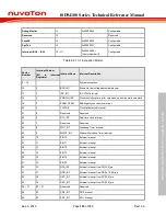
The Table 6.2.13-1 lists the exception model supported by ISD94100 Series. Software can set 16
levels of priority on some of these exceptions as well as on all interrupts. The highest user-
configurable priority is denoted as “0x00” and the lowest priority is denoted as “0xF0” (The 4-LSB
always 0). The default priority of all the user-configurable interrupts is “0x00”. Note that priority “0”
is treated as the fourth priority on the system, after three system exceptions “Reset”, “NMI” and
“Hard Fault”.
When any interrupts is accepted, the processor will automatically fetch the starting address of the
interrupt service routine (ISR) from a vector table in memory. On system reset, the vector table is
fixed at address 0x00000000. Privileged software can write to the VTOR to relocate the vector table
start address to a different memory location, in the range 0x00000080 to 0x3FFFFF80,
The vector table contains the initialization value for the stack pointer on reset, and the entry point
addresses for all exception handlers. The vector number on previous page defines the order of
entries in the vector table associated with exception handler entry as illustrated in previous section.
Exception Type
Vector Number
Vector Address
Priority
Reset
1
0x00000004
-3
NMI
2
0x00000008
-2
Hard Fault
3
0x0000000C
-1
Memory Manager Fault
4
0x00000010
Configurable
Bus Fault
5
0x00000014
Configurable
Usage Fault
6
0x00000018
Configurable
Reserved
7 ~ 10
Reserved
SVCall
11
0x0000002C
Configurable
Содержание ISD94100 Series
Страница 528: ...ISD94100 Series Technical Reference Manual Sep 9 2019 Page 528 of 928 Rev1 09 ISD94100 SERIES TECHNICAL REFERENCE MANUAL...
Страница 626: ...ISD94100 Series Technical Reference Manual Sep 9 2019 Page 626 of 928 Rev1 09 ISD94100 SERIES TECHNICAL REFERENCE MANUAL...
Страница 702: ...ISD94100 Series Technical Reference Manual Sep 9 2019 Page 702 of 928 Rev1 09 ISD94100 SERIES TECHNICAL REFERENCE MANUAL...
Страница 875: ...ISD94100 Series Technical Reference Manual Sep 9 2019 Page 875 of 928 Rev1 09 ISD94100 SERIES TECHNICAL REFERENCE MANUAL...


