ISD94100 Series Technical Reference Manual
Sep 9, 2019
Page
506
of 928
Rev1.09
IS
D
9
410
0
S
ER
IE
S
T
E
C
HN
ICA
L
RE
F
E
RE
NCE
M
AN
U
AL
[20]
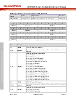
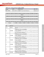
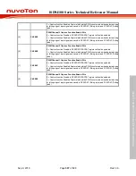
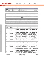
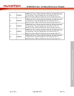
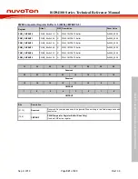
RCRLDEN4
PWM Channel 4 Rising Capture Reload Enable Bits
0 = Rising capture reload counter Disabled.
1 = Rising capture reload counter Enabled.
[19]
RCRLDEN3
PWM Channel 3 Rising Capture Reload Enable Bits
0 = Rising capture reload counter Disabled.
1 = Rising capture reload counter Enabled.
[18]
RCRLDEN2
PWM Channel 2 Rising Capture Reload Enable Bits
0 = Rising capture reload counter Disabled.
1 = Rising capture reload counter Enabled.
[17]
RCRLDEN1
PWM Channel 1 Rising Capture Reload Enable Bits
0 = Rising capture reload counter Disabled.
1 = Rising capture reload counter Enabled.
[16]
RCRLDEN0
PWM Channel 0 Rising Capture Reload Enable Bits
0 = Rising capture reload counter Disabled.
1 = Rising capture reload counter Enabled.
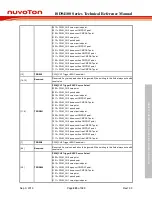
[15:14]
Reserved
Reserved. Any values read should be ignored. When writing to this field always write with
reset value.
[13]
CAPINV5
PWM Channel 5 Capture Inverter Enable Bits
0 = Capture source inverter Disabled.
1 = Capture source inverter Enabled. Reverse the input signal from GPIO.
[12]
CAPINV4
PWM Channel 4 Capture Inverter Enable Bits
0 = Capture source inverter Disabled.
1 = Capture source inverter Enabled. Reverse the input signal from GPIO.
[11]
CAPINV3
PWM Channel 3 Capture Inverter Enable Bits
0 = Capture source inverter Disabled.
1 = Capture source inverter Enabled. Reverse the input signal from GPIO.
[10]
CAPINV2
PWM Channel 2 Capture Inverter Enable Bits
0 = Capture source inverter Disabled.
1 = Capture source inverter Enabled. Reverse the input signal from GPIO.
[9]
CAPINV1
PWM Channel 1 Capture Inverter Enable Bits
0 = Capture source inverter Disabled.
1 = Capture source inverter Enabled. Reverse the input signal from GPIO.
[8]
CAPINV0
PWM Channel 0 Capture Inverter Enable Bits
0 = Capture source inverter Disabled.
1 = Capture source inverter Enabled. Reverse the input signal from GPIO.
[7:6]
Reserved
Reserved. Any values read should be ignored. When writing to this field always write with
reset value.
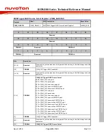
[5]
CAPEN5
PWM Channel 5 Capture Function Enable Bits
0 = Capture function Disabled. RCAPDAT/FCAPDAT register will not be updated.
1 = Capture function Enabled. Capture latched the PWM counter value when detected rising
or falling edge of input signal and saved to RCAPDAT (Rising latch) and FCAPDAT (Falling
latch).
[4]
CAPEN4
PWM Channel 4 Capture Function Enable Bits
0 = Capture function Disabled. RCAPDAT/FCAPDAT register will not be updated.
Содержание ISD94100 Series
Страница 528: ...ISD94100 Series Technical Reference Manual Sep 9 2019 Page 528 of 928 Rev1 09 ISD94100 SERIES TECHNICAL REFERENCE MANUAL...
Страница 626: ...ISD94100 Series Technical Reference Manual Sep 9 2019 Page 626 of 928 Rev1 09 ISD94100 SERIES TECHNICAL REFERENCE MANUAL...
Страница 702: ...ISD94100 Series Technical Reference Manual Sep 9 2019 Page 702 of 928 Rev1 09 ISD94100 SERIES TECHNICAL REFERENCE MANUAL...
Страница 875: ...ISD94100 Series Technical Reference Manual Sep 9 2019 Page 875 of 928 Rev1 09 ISD94100 SERIES TECHNICAL REFERENCE MANUAL...

