ISD94100 Series Technical Reference Manual
Sep 9, 2019
Page
76
of 928
Rev1.09
IS
D
9
410
0
S
ER
IE
S
T
E
C
HN
ICA
L
RE
F
E
RE
NCE
M
AN
U
AL
Bits
Description
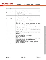
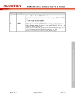
[7]
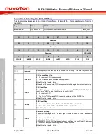
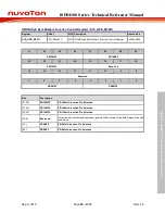
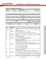
LVREN
Low Voltage Reset Enable Bit (Write Protected)
The LVR function resets the chip when the input power voltage is lower than LVR circuit
setting. LVR function is enabled by default.
0 = Low Voltage Reset function Disabled.
1 = Low Voltage Reset function Enabled.
Note:
This bit is write protected. Refer to the SYS_REGLCTL register.
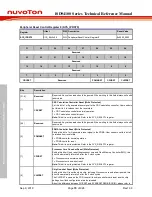
[6]
BODOUT
Brown-out Detector Output Status
0 = Brown-out Detector output status is 0.
The detected voltage is higher than BODVL setting or BODEN is 0.
1 = Brown-out Detector output status is 1.
The detected voltage is lower than BODVL setting.
If the BODEN is 0, BOD function is disabled and this bit will be 0.
[5]
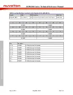
BODLPM
Brown-out Detector Low Power Mode (Write Protected)
0 = BOD operate in normal mode (default).
1 = BOD Low Power mode Enabled.
Note 1:
The low power mode can reduce the current to about 1/10 but slow the BOD
response.
Note 2:
This bit is write protected. Refer to the SYS_REGLCTL register.
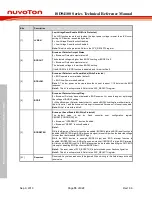
[4]
BODIF
Brown-out Detector Interrupt Flag
0 = Brown-out Detector has not detected a BOD event on V
DD
down through or up through
the voltage of BODVL setting.
1 = When Brown-out Detector detects that V
DD
crosses BODLVL setting from either direction,
this bit is set to 1 and the brown-out interrupt is requested if brown-out interrupt is enabled.
Note:
Write 1 to clear this bit to 0.
[3]
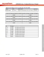
BODRSTEN
Brown-out Reset Enable Bit (Write Protected)
The default value is set by flash controller user configuration register
CBORST(CONFIG0[20]) bit .
0 = Brown-out “INTERRUPT” function Enabled.
1 = Brown-out “RESET” function Enabled.
Note 1:
While the Brown-out Detector function is enabled (BODEN high) and BOD reset function is
enabled (BODRSTEN high), BOD will assert a signal to reset chip when the detected voltage
is lower than the threshold (BODOUT high).
While the BOD function is enabled (BODEN high) and BOD interrupt function is
enabled (BODRSTEN low), BOD will assert an interrupt if BODOUT is high. BOD interrupt
will latch until BODEN is set to 0. BOD interrupt can be blocked by disabling the NVIC BOD
interrupt or disabling BOD function (set BODEN low).
Note 2:
The reset value of SYS_BODCTL[3] is determined by user flash configuration.
Note 3:
This bit is write protected. Refer to the SYS_REGLCTL register.
[2:1]
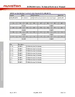
Reserved
Reserved. Any values read should be ignored. When writing to this field always write with
reset value.
Содержание ISD94100 Series
Страница 528: ...ISD94100 Series Technical Reference Manual Sep 9 2019 Page 528 of 928 Rev1 09 ISD94100 SERIES TECHNICAL REFERENCE MANUAL...
Страница 626: ...ISD94100 Series Technical Reference Manual Sep 9 2019 Page 626 of 928 Rev1 09 ISD94100 SERIES TECHNICAL REFERENCE MANUAL...
Страница 702: ...ISD94100 Series Technical Reference Manual Sep 9 2019 Page 702 of 928 Rev1 09 ISD94100 SERIES TECHNICAL REFERENCE MANUAL...
Страница 875: ...ISD94100 Series Technical Reference Manual Sep 9 2019 Page 875 of 928 Rev1 09 ISD94100 SERIES TECHNICAL REFERENCE MANUAL...


