ISD94100 Series Technical Reference Manual
Sep 9, 2019
Page
195
of 928
Rev1.09
IS
D
9
410
0
S
ER
IE
S
T
E
C
HN
ICA
L
RE
F
E
RE
NCE
M
AN
U
AL
LDROM
LDROM is designed for a loader to implement In-System-Programming (ISP) function. It is a 4 KB
size flash memory region, the range of address from 0x0010_0000 to 0x0010_0FFF.
Configuration Bytes
The ISD94100 device provides 3-words of flash memory, from address 0x0030_0000 to store
system configuration such as logic, flash security lock, boot select, brown-out voltage level, Data
Flash base address, etc. The configuration bytes take effect after system reset.
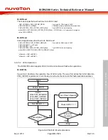
User can call normal FMC single word read function to read these configuration bytes. To update
these configuration bytes, user shall first set CFGUEN bit in FMC_ISPCTL register, and then call
FMC Erase followed by FMC Write function to complete the update.
Refer to Table CONFIG0, CONFIG1 and CONFIG2 in Register Description section for details of the
configuration bits.
Block Name
Size
Start Address
End Address
APROM
(512-4*N) KB
0x0000_0000
0x0007_FFFF(512 KB, if DFEN=1)
DFBADR-1 (if DFEN=0)
Data Flash
4*N KB
(if DFEN=0)
DFBADR
(if DFEN=0)
0x0007_FFFF (512 Kbytes)
LDROM
4 KB
0x0010_0000
0x0010_0FFF
User
Configuration
3 words
0x0030_0000
0x0030_000B
Note:
N is the page number of configured data flash. One page size is 4096 bytes, N >= 0
Table 6.4.4-1 Flash Memory Address Map
6.4.4.2
Boot Configuration
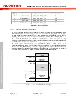
Typically the system vector table is located in ROM space from 0x0000_0000 to 0x0000_01FF.
When the processor exits from reset, it loads the MSP (Main Stack Pointer) from address
0x0000_0000, and loads the PC counter with the value pointed of the RESET Vector, which is stored
at address 0x0000_0004. The processor then starts to fetch code from the address pointed to by
the RESET vector and program execution begins.
The ISD94100 device has the capability of mapping vector table into APROM space from
0x0000_0000 to 0x0000_01FF, or into LDROM space from 0x0010_0000 to 0x0010_01FF. Thus
provides the flexibly of booting from APROM or from LDROM.
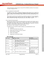
The ISD94100 device supports In Application Programming (IAP) function that the device can
update its own firmware when it is running. By booting into IAP mode, without JTAG involved, the
device can re-program other parts of the ROM (APROM, LDROM or Data Flash). Under IAP mode
the ISD94100 series device supports remapping function. That is, (typically after IAP programming
is finished) the MCU can issue re-mapping to dynamically change the data and code read access,
so that the MCU can switch execution from LDROM, APROM or SRAM.
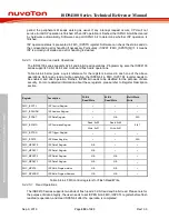
Through CBS[1:0] bits in CONFIG0, the ISD94100 series offers four boot configurations, as shown
in Table 6.4.4-2.
Содержание ISD94100 Series
Страница 528: ...ISD94100 Series Technical Reference Manual Sep 9 2019 Page 528 of 928 Rev1 09 ISD94100 SERIES TECHNICAL REFERENCE MANUAL...
Страница 626: ...ISD94100 Series Technical Reference Manual Sep 9 2019 Page 626 of 928 Rev1 09 ISD94100 SERIES TECHNICAL REFERENCE MANUAL...
Страница 702: ...ISD94100 Series Technical Reference Manual Sep 9 2019 Page 702 of 928 Rev1 09 ISD94100 SERIES TECHNICAL REFERENCE MANUAL...
Страница 875: ...ISD94100 Series Technical Reference Manual Sep 9 2019 Page 875 of 928 Rev1 09 ISD94100 SERIES TECHNICAL REFERENCE MANUAL...


