ISD94100 Series Technical Reference Manual
Sep 9, 2019
Page
270
of 928
Rev1.09
IS
D
9
410
0
S
ER
IE
S
T
E
C
HN
ICA
L
RE
F
E
RE
NCE
M
AN
U
AL
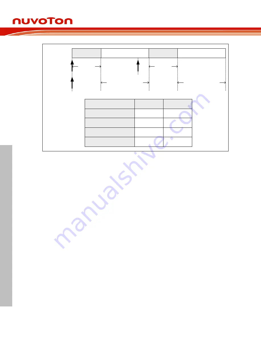
Channel 1
Channel 0
Channel 1
Channel 0
CH1 Request
CH0 Request
Transferred
1 byte data
Transferred
128 words data
Transferred
1 byte data
Transferred
128 words data
CH1
CH0
127
255
TXCNT
(PDMA_DSCTn_CTL[31:16])
0
(1 byte)
2
(1 word)
TXWIDTH
(PDMA_DSCTn_CTL[13:12])
Execution
Channel
BURSIZE
(PDMA_DSCTn_CTL[6:4])
Non-useful
0
(128 transfers)
1
(Single Transfer)
0
(Burst Transfer)
TXTYPE
(PDMA_DSCTn_CTL[2])
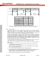
Figure 6.6-6 Example of Single Transfer Type and Burst Transfer Type in Basic Mode
6.6.5.4
Channel Time-out
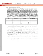
Only PDMA channel 0 and channel 1 support time-out function. When the transfer channel is
enabled and selected to the peripheral, corresponding channel time-out TOUTENn
(PDMA_TOUTEN [n], n=0,1) is enabled, then channel’s corresponding time-out counter will start
count up from 0 while the channel has received trigger signal from the peripheral.
The time-out counter is based on output of HCLK prescaler, which is setting by corresponding
channel’s TOUTPSCn (PDMA_TOUTPSC [2+4n:4n], n=0,1). If time-out counter counts up from 0
to corresponding channel’s TOCn (PDMA_TOC0_1 [16(n+1)-1):16n], n=0,1), the PDMA controller
will generate interrupt signal when corresponding TOUTIENn (PDMA_TOUTIEN [n], n=0,1) is
enabled. When time-out occurred, corresponding channel’s REQTOFn (PDMA_INTSTS [n+8],
n=0,1) will be set to indicate channel time-out is happened.
Time-out counter reset to 0 while counter count to TOCn (PDMA_TOC0_1 [16(n+1)-1:16n], n=0,1),
received trigger signal, time-out function disabled or chip enter power-down mode.
Figure 6.6-7 shows an example about time-out counter operation. The operation sequence is
described below:
1. The channel 0 time-out counter is not counting when time-out function is enabled by set
TOUTEN0(PDMA_TOUTEN[0]) bit to 1.
2. Time-out counter is start counting from 0 to the value of TOC0(PDMA_TOC0_1[15:0]) bits
when received first peripheral request.
3. Time-out counter is reset to 0 by received second peripheral request.
4. Channel 0 request time-out flag(REQTOF0(PDMA_INTSTS[8])) is set to high when time-out
counter counts to 5. The counter will keep counting from 0 to 5, and user can clear
REQTOF0 flag then polling REQTOF0 flag to check next time-out occurred.
5. Time-out counter is reset to 0 when time-out function is disabled.
Содержание ISD94100 Series
Страница 528: ...ISD94100 Series Technical Reference Manual Sep 9 2019 Page 528 of 928 Rev1 09 ISD94100 SERIES TECHNICAL REFERENCE MANUAL...
Страница 626: ...ISD94100 Series Technical Reference Manual Sep 9 2019 Page 626 of 928 Rev1 09 ISD94100 SERIES TECHNICAL REFERENCE MANUAL...
Страница 702: ...ISD94100 Series Technical Reference Manual Sep 9 2019 Page 702 of 928 Rev1 09 ISD94100 SERIES TECHNICAL REFERENCE MANUAL...
Страница 875: ...ISD94100 Series Technical Reference Manual Sep 9 2019 Page 875 of 928 Rev1 09 ISD94100 SERIES TECHNICAL REFERENCE MANUAL...

