ISD94100 Series Technical Reference Manual
Sep 9, 2019
Page
425
of 928
Rev1.09
IS
D
9
410
0
S
ER
IE
S
T
E
C
HN
ICA
L
RE
F
E
RE
NCE
M
AN
U
AL
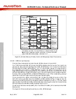
PWM period
PWM period
PWM period
PWM period
PWM period
PWM period
PWM period
PWM period
PWM period
CH0_PERIOD = 900
CH2_PERIOD = 900
CH4_PERIOD = 900
CH0_PERIOD = 600
CH2_CMPDAT = 600
CH4_CMPDAT = 600
PWM SYNC input
PHS = 0
(PWM_PHS0)
PWM_CH0
PWM_CH2
PWM_CH4
PHSDIR0 = 1
(PWM_SYNC[24])
PHSDIR2 = 0
(PWM_SYNC[25])
PHSDIR4 = 1
(PWM_SYNC[26])
PHS = 600
(PWM_PHS2)
PHS = 600
(PWM_PHS4)
SYNC PHS & PHSDIR Load
Note:
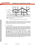
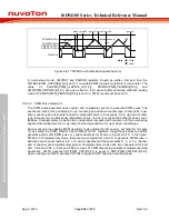
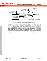
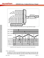
Figure 6.8-25 PWM Synchronous Function with Synchronize source from SYNC_IN Signal
6.8.5.20 PWM Output Control
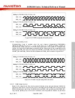
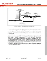
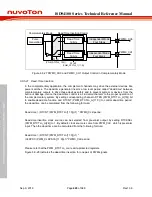
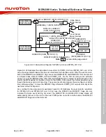
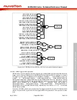
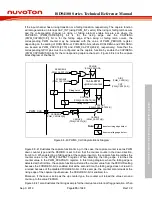
After PWM pulse generation, there are four to six steps to control the output of PWM channels. In
independent mode, there are Mask, Brake, Pin Polarity and Output Enable four steps as shown in
Figure 6.8-26. In complementary mode, it needs two more steps to precede these four steps,
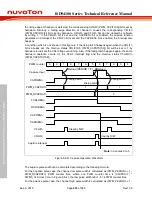
Complementary channels and Dead-Time Insertion as shown in Figure 6.8-27.
Mask Data
MSKDAT0
(PWM_MSK[0])
PINV0
(PWM_POLCTL[0])
POEN0
(PWM_POEN[0])
Brake
BRKAEVEN
(PWM_BRKCTL0_1[17:16])
PWM_BRKCTL0_1[15:0]
Pulse
Generation
MSKEN0
(PWM_MSKEN[0])
PWM0_CH0
Independent Mode 4 Steps
Mask
Brake
Enable
Polarity
Figure 6.8-26 PWM0_CH0 Output Control in Independent Mode
Содержание ISD94100 Series
Страница 528: ...ISD94100 Series Technical Reference Manual Sep 9 2019 Page 528 of 928 Rev1 09 ISD94100 SERIES TECHNICAL REFERENCE MANUAL...
Страница 626: ...ISD94100 Series Technical Reference Manual Sep 9 2019 Page 626 of 928 Rev1 09 ISD94100 SERIES TECHNICAL REFERENCE MANUAL...
Страница 702: ...ISD94100 Series Technical Reference Manual Sep 9 2019 Page 702 of 928 Rev1 09 ISD94100 SERIES TECHNICAL REFERENCE MANUAL...
Страница 875: ...ISD94100 Series Technical Reference Manual Sep 9 2019 Page 875 of 928 Rev1 09 ISD94100 SERIES TECHNICAL REFERENCE MANUAL...


