ISD94100 Series Technical Reference Manual
Sep 9, 2019
Page
412
of 928
Rev1.09
IS
D
9
410
0
S
ER
IE
S
T
E
C
HN
ICA
L
RE
F
E
RE
NCE
M
AN
U
AL
DIRF
(PWM_CNTn[16])
0
1
2
3
4
3
1
2
0
1
2
3
4
3
1
2
0
5
6
7
6
4
5
1
2
3
4
PWM Period
PERIOD = 4
CMPDAT = 4
PERIOD = 7
CMPDAT = 5
PWM Period
Up-count compared
point event (CMPU)
Down-count compared
point event (CMPD)
PERIOD = 5
CMPDAT= 0
CNT
(PWM_CNTn[15:0])
Note1:
No CMPU event occurred when CMPDAT equals to PERIOD.
Note2:
n denotes channel 0,1..5
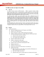
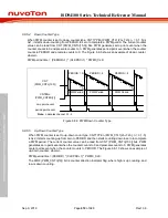
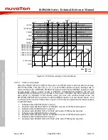
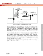
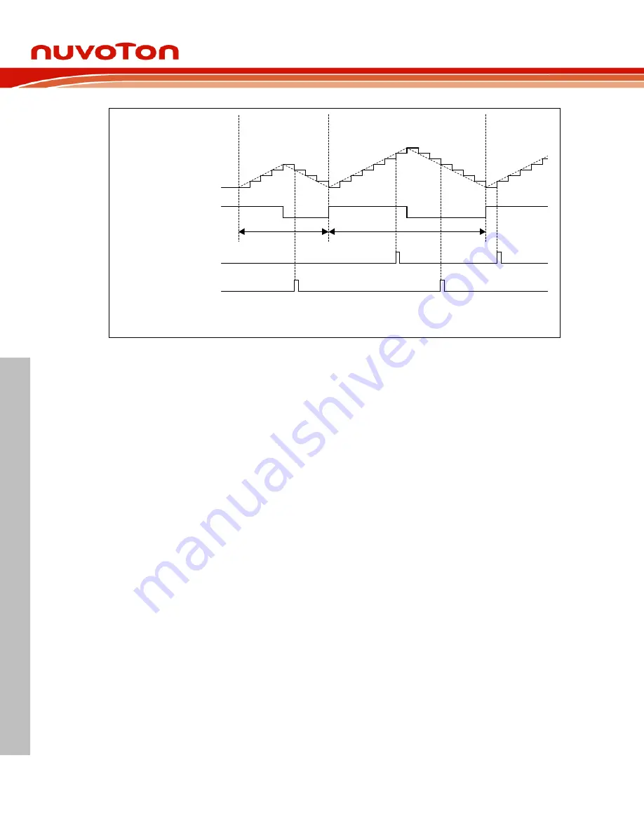
Figure 6.8-11 PWM Compared point Events in Up-Down Counter Type
FTCMPDAT is a free trigger comparator register. Each complementary paired channel only
supports one free trigger comparator. The value of FTCMPDATn_m( n = 0,2,4, m = 1,3,5) register
is continuously compared to even channel’s counter value. When counter is equal to the value of
FTCMPDAT register, PWM generates an event and only uses to trigger EADC.
6.8.5.7
PWM Double Buffering
The double buffering uses double buffers to separate software writing and hardware action
operation timing. There are four loading modes for loading values to buffer: period loading mode,
immediately loading mode, window loading mode and center loading mode. After registers are
modified through software, hardware will load register value to the buffer register according to the
loading mode timing. The hardware action is based on the buffer value.
This can prevent
asynchronous operation problem due to software and hardware asynchronicity.
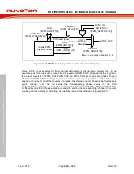
The PWM provides PBUF (PWM_PBUFn[15:0]) as the active PERIOD buffer register, CMPBUF
(PWM_CMPBUFn[15:0]) as the active CMPDAT buffer register, FTCMPBUF
(PWM_FTCMPBUFn_m[15:0]) as the active FTCMPDAT buffer register and CPSCBUF
(PWM_CPSCBUFn_m[15:0]) as the active CLKPSC buffer register. The concept of double
buffering is used in loading modes, which are described in the following sections. For example, as
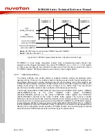
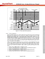
shown Figure 6.8-12, in period loading mode, writing PERIOD, CMPDAT and FTCMPDAT registers
through software, PWM will load new values to their buffer PBUF (PWM_PBUFn[15:0]), CMPBUF
(PWM_CMPBUFn[15:0]) and FTCMPBUF (PWM_FTCBUF[15:0]) at start of the next period without
affecting the current period counter operation. FTCMPU denotes up-count free trigger compared
point event and FTCMPD denotes down-count free trigger compared event.
Содержание ISD94100 Series
Страница 528: ...ISD94100 Series Technical Reference Manual Sep 9 2019 Page 528 of 928 Rev1 09 ISD94100 SERIES TECHNICAL REFERENCE MANUAL...
Страница 626: ...ISD94100 Series Technical Reference Manual Sep 9 2019 Page 626 of 928 Rev1 09 ISD94100 SERIES TECHNICAL REFERENCE MANUAL...
Страница 702: ...ISD94100 Series Technical Reference Manual Sep 9 2019 Page 702 of 928 Rev1 09 ISD94100 SERIES TECHNICAL REFERENCE MANUAL...
Страница 875: ...ISD94100 Series Technical Reference Manual Sep 9 2019 Page 875 of 928 Rev1 09 ISD94100 SERIES TECHNICAL REFERENCE MANUAL...

