


634
37 FUNCTIONS
37.2 Tracking Transfer
■
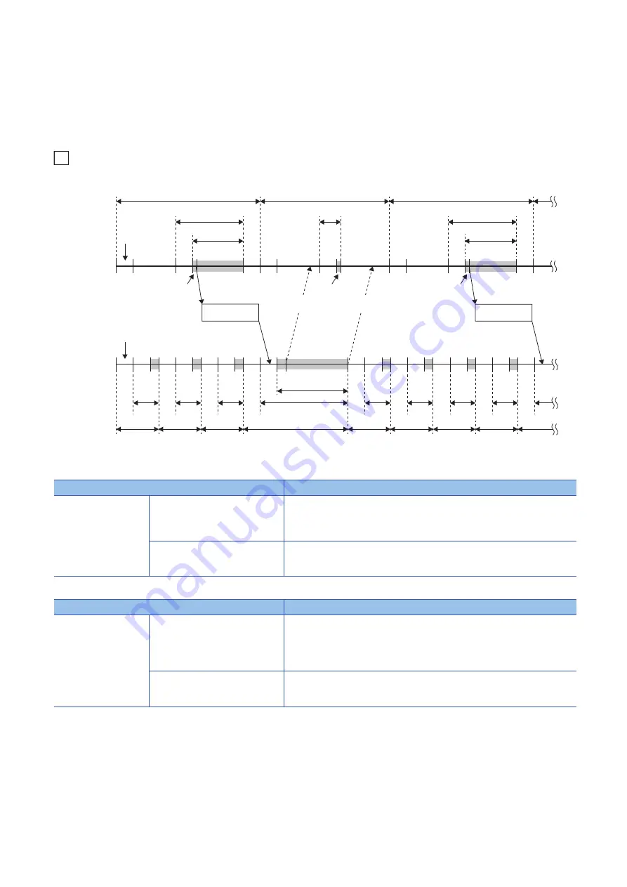
Asynchronous tracking mode
In the asynchronous tracking mode, the control system starts the next scan without waiting for notifications of data reception/
reflection completion from the standby system.
Unlike the synchronous tracking mode, the scan time is not affected by waiting time for data reception/reflection completion.
When the standby system does not receive the tracking data from the control system, the standby system starts the next
scan.
Ex.
When the control system CPU module is in the RUN state and the standby system CPU module is in the STOP state
*1 If the constant scan is used, waiting time for the constant scan generated.
In the control system, the scan time is extended by the following tracking send processing time.
In the standby system, the scan time increases by the following tracking receive processing time.
■
When the mode is switched from the asynchronous tracking mode to the synchronous
tracking mode
When the mode is switched from the asynchronous tracking mode to the synchronous tracking mode, the standby system
receives the tracking data twice in one scan. Therefore, the scan time of the standby system is extended by the following time.
Scan time of the standby system: Standby system scan time
2 + Control system scan time
Item
Description
(1) Tracking send
processing
(2) Waiting for completion of tracking
data reflection
After receiving a notification of the reflection completion from the standby system, the
control system sends the tracking data.
When a notification of reflection completion is not arrived (4), the control system does
not send tracking data in the scan.
(3) Sending tracking data
The control system sends the tracking data. After completing the send, the control
system starts another END processing without waiting for a notification of receive
completion from the standby system.
Item
Description
(5) Tracking receive
processing
(6) Waiting for tracking data reception
The standby system receives the tracking data from the control system. When the
standby system does not receive the tracking data, the standby system starts the next
scan.
After receiving the tracking data, the standby system notifies the control system of the
receive completion and reflects the tracking data.
(7) Reflecting tracking data
The standby system reflects the tracking data. After the reflection completion, the
standby system notifies the control system of the reflection completion and starts the
next scan.
(1)
END
(6)
(6)
(6)
(6)
(6)
(6)
(6)
(6)
(5)
(7)
MAIN
MAIN
MAIN
(2)
(3)
END
(2)
(2)
(1)
(3)
END
END
END
END
END
END
END
END
END
(4)
END
*1
*1
*1
Scan time of the control system CPU module
Tracking data
Control system
CPU module
Standby system
CPU module
Scan time of the standby system CPU module
I/O refresh
(input only)
I/O refresh
Tracking data
Data
received
Data
reflected
Содержание MELSEC iQ-R-R00CPU
Страница 2: ......
Страница 151: ...9 MONITOR FUNCTION 9 1 Real Time Monitor Function 149 9 MEMO ...
Страница 323: ...18 SEQUENCE SCAN SYNCHRONIZATION SAMPLING FUNCTION 321 18 MEMO ...
Страница 330: ...328 20 ROUTING SETTING 20 3 Precautions MEMO ...
Страница 423: ...26 BASIC CONCEPT 26 8 State Transition of the Redundant System 421 26 MEMO ...
Страница 524: ...522 30 MAINTENANCE AND INSPECTION FOR A REDUNDANT SYSTEM 30 1 Module Replacement in the Redundant System MEMO ...
Страница 1009: ...APPX Appendix 14 List of Available SQL Commands for CPU Module Database Access Function 1007 A MEMO ...
Страница 1014: ...1012 APPX Appendix 15 Added and Enhanced Functions MEMO ...
Страница 1027: ......


