567
4
P
RACTICAL CIRC
UI
T
S
PRACTICAL CIRCUITS
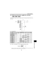
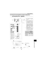
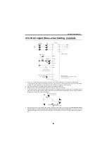
4.4.3
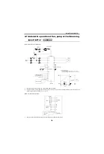
Using pulse I/O
(A700)
*1
You can make adjustment to match the output frequency
of the inverters regarding [
Pr. 385
,
Pr. 386
]. The ratio can
be changed to make adjustment.
*2
When two or more motors are coupled mechanically,
larger load may be applied to one motor, resulting in
overload. Use the method described on page 565.
*3
When the power supply is 400V class, install a step-
down transformer.
*4
Use [
Pr. 291
] to set the FM terminal output to "high speed
pulse train output (ON width is always same)". Perform
wiring terminal FM on the master side and terminal JOG
on the slave side after setting [
Pr. 291
].
*5
Use [
Pr. 291
] to set the JOG terminal input to "pulse train
input". In addition, to input the highest pulse train of
50kpulse/s, set [
Pr. 384 = 125
].
Refer to page 228.
*6
When the wiring length between FM and JOG is long, input
pulse can not be recognized because of a pulse shape
deformation due to the stray capacitances of the wiring.
When wiring length is long (10m or more of recommended
0.75mm
2
twisted cable), connect terminal JOG and terminal
PC using an external pull up resistance. The reference of
resistance value to the wiring length is as in the table below.
Stray capacitances of the wiring greatly differ according to
the cable type and cable laying, the above cable length is
not a guaranteed value.
When using a pull up resistance, check the permissible
power of the resistor and permissible load current (terminal
PC:100mA, high speed pulse train output:85mA) and use
them within a permissible range.
*7
A pulse transmission delay in a slave is approximately 1
to 2 s. When wiring length is long, the delay further
increases.
*8
The inverter can be operated by pulse train input as
frequency command.
A700
IM
U
V
W
R
S
T
MCCB
MC
M
C
F
T
*3
B
C
B C
MC
B
C
10
2
5
IM
U
V
W
R
S
T
SD
JOG
PC
10
2
5
Pull-up
resistance
*6
B
C
STF
SD
FM
*4
*5
STF
*8
(
5V)
ON
OFF
Ready
Inverter No. 1
fault signal
Inverter No. 2
fault signal
Power
supply
Frequency setting
potentiometer
2W1k
Inverter No. 1
Ground
Inverter No. 2
Ground
Motor
Start signal
Motor
Fault signal
Related parameters
Terminal 2 frequency setting gain frequency [
Pr. 125
]
Fault signal
closed when normal
opened when faulty
Pulse train I/O selection [
Pr. 291
]
Input pulse division scaling factor [
Pr. 384
]
Frequency for zero input pulse [
Pr. 385
]
Frequency for maximum input pulse [
Pr. 386
]
(Master)
(Slave)
Wiring Length
Less than 10m
10 to 50m
50 to 100m
Pull up resistance
Not necessary
1k
Ω
470
Ω
Load current (for reference)
10mA
35mA
65mA
Содержание FR-A700 Series
Страница 245: ...279 2 PARAMETER PARAMETER MEMO ...
Страница 440: ...474 PARAMETER MEMO ...
Страница 522: ...556 SELECTION MEMO ...


