578
PRACTICAL CIRCUITS
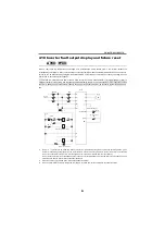
4.10 Inverter fault output display and failure reset
(A700,
F700)
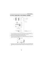
When a fault such as overcurrent, overvoltage, and instantaneous power failure occurs, the inverter outputs the
corresponding fault signal. A relay contact is used to output the fault signal and is actuated (turned ON) when a fault occurs.
This relay can be deactivated by using the reset terminal RES of the inverter. It may also be reset by switching OFF the
inverter power. For details refer to page 57.
When the FR-A700 series 22K or less is used for cyclic or heavy duty operation, it is recommended to install a
magnetic contactor in the primary side to prevent the brake discharge resistor from overheat/burnout if the regenerative brake
transistor is damaged due to the thermal capacity shortage of the discharge resistor, an excessive regenerative brake duty,
etc.
*1
Set [
Pr. 75
= 1] "Reset can be made only when a fault occurs" to disable resetting the inverter during normal operation. (If the
inverter is reset during normal operation, the motor coasts to a stop. This setting is made to prevent the inverter from resulting
in an over current alarm if the motor is still coasting when the inverter has returned from the reset status.)
Do not press the inverter reset pushbutton unless required. It is recommended to provide the failure reset pushbutton of the
external device and the inverter reset pushbutton individually.
*2
When the power supply is 400V class, install a step-down transformer.
*3
When an alarm indication is held, always remove jumpers or cables from across terminals R-R1 and across S-S1.
A700 F700
A700
IM
U
V
W
R
S
T
Earth (Ground)
MCCB
T
*2
OFF
ON
RE
MC
R
E
B
C
STF(STR)
RES
SD
R1
S1
MC
F
T
T
MC
*3
Power
supply
Inverter
Motor
Start switch
(Inverter reset)
PB
(Coasting interlock timer)
Ready
Failure indicator lamp
RE
M
C
Содержание FR-A700 Series
Страница 245: ...279 2 PARAMETER PARAMETER MEMO ...
Страница 440: ...474 PARAMETER MEMO ...
Страница 522: ...556 SELECTION MEMO ...


