575
4
P
RACTICAL CIRC
UI
T
S
PRACTICAL CIRCUITS
4.8 Positioning operation
(common)
*1
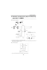
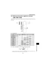
When the speed commands H, M and L are turned on simultaneously, the lower speed has precedence in operation.
[Example] When the speed commands H and L are turned ON simultaneously, the low speed command L is used in operation.
As
do not have many input terminals, speed command can be input to only two terminals.
*2
The
7.5K or less has a built-in discharging resistor designed for regenerative braking, but in the above diagram it was
replaced by a high-duty brake resistor.
the 22K or less, and
0.4K to 15K have a built-in brake transistor
and a high duty brake resistor can be connected. (For the
, an external discharging resistor for regenerative braking can
not be used.)
*3
Also refer to the circuit example of the motor equipped with brake. (Refer to page 564)
*4
When an inverter with a regenerative brake resistor is used for cyclic or heavy duty operation, it is recommended to install a
magnetic contactor in the primary side to prevent the discharging resistor from overheat/burnout if the regenerative brake
transistor is damaged due to the thermal capacity shortage of the discharging resistor, and excessive regenerative brake duty,
etc.
*5
When the power supply is 400V class, install a step-down transformer.
*6
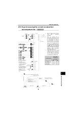
In this circuit, pressing the stop button stops the motor with the electromagnetic brake. For operation of the electromagnetic
brake after the motor is decelerated by the inverter, refer to page 576.
common
U
V
W
R
S
T
MCCB
T
*5
F
BR
B
F
R
IM
PB
PB
LS
F
PB
LS
R
P
PX
PR
F
R
B
R
F
R
H
M
L
F
R
R
F
B
C
RH
RM
RL
SD
STF
STR
SD
MRS
R
MC
ޓ
*4
High-duty brake resistor
*
Power
supply
High speed
Middle speed
Low speed
Inverter
Brake
Motor
Ground
Speed
High speed
Middle speed
Low speed
Time
"H" ON
"M"ON
"L" ON
"LS"ON
F or R is ON.
Operation pattern
Stop
Forward
rotation
Reverse
rotation
Note: When the brake resistor is
fitted to the
externally, always remove the
link from across terminals
PX-PR to prevent the brake
transistor from being
A700
*1
*1
*1
D700
A700
A700
E700
D700
F700
Содержание FR-A700 Series
Страница 245: ...279 2 PARAMETER PARAMETER MEMO ...
Страница 440: ...474 PARAMETER MEMO ...
Страница 522: ...556 SELECTION MEMO ...


